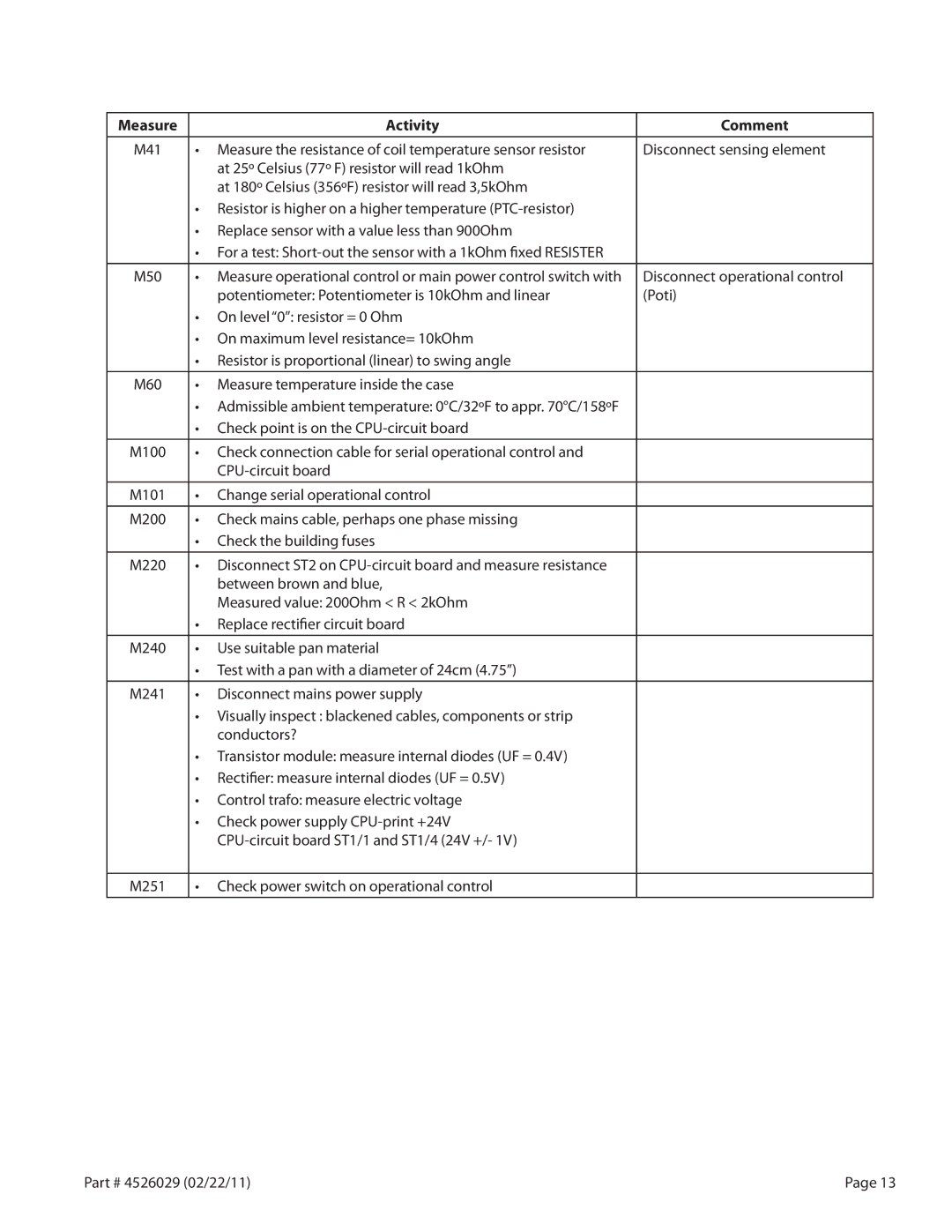
Measure | Activity | Comment |
|
|
|
M41 | • Measure the resistance of coil temperature sensor resistor | Disconnect sensing element |
| at 25º Celsius (77º F) resistor will read 1kOhm |
|
| at 180º Celsius (356ºF) resistor will read 3,5kOhm |
|
| • Resistor is higher on a higher temperature |
|
| • Replace sensor with a value less than 900Ohm |
|
| • For a test: |
|
M50 | • Measure operational control or main power control switch with | Disconnect operational control |
| potentiometer: Potentiometer is 10kOhm and linear | (Poti) |
| • On level “0”: resistor = 0 Ohm |
|
| • On maximum level resistance= 10kOhm |
|
| • Resistor is proportional (linear) to swing angle |
|
|
|
|
M60 | • Measure temperature inside the case |
|
| • Admissible ambient temperature: 0°C/32ºF to appr. 70°C/158ºF |
|
| • Check point is on the |
|
|
|
|
M100 | • Check connection cable for serial operational control and |
|
|
| |
|
|
|
M101 | • Change serial operational control |
|
M200 | • Check mains cable, perhaps one phase missing |
|
| • Check the building fuses |
|
|
|
|
M220 | • Disconnect ST2 on |
|
| between brown and blue, |
|
| Measured value: 200Ohm < R < 2kOhm |
|
| • Replace rectifier circuit board |
|
|
|
|
M240 | • Use suitable pan material |
|
| • Test with a pan with a diameter of 24cm (4.75”) |
|
M241 | • Disconnect mains power supply |
|
| • Visually inspect : blackened cables, components or strip |
|
| conductors? |
|
| • Transistor module: measure internal diodes (UF = 0.4V) |
|
| • Rectifier: measure internal diodes (UF = 0.5V) |
|
| • Control trafo: measure electric voltage |
|
| • Check power supply |
|
|
| |
|
|
|
M251 | • Check power switch on operational control |
|
|
|
|
Part # 4526029 (02/22/11) | Page 13 |
