III. Hardware Description
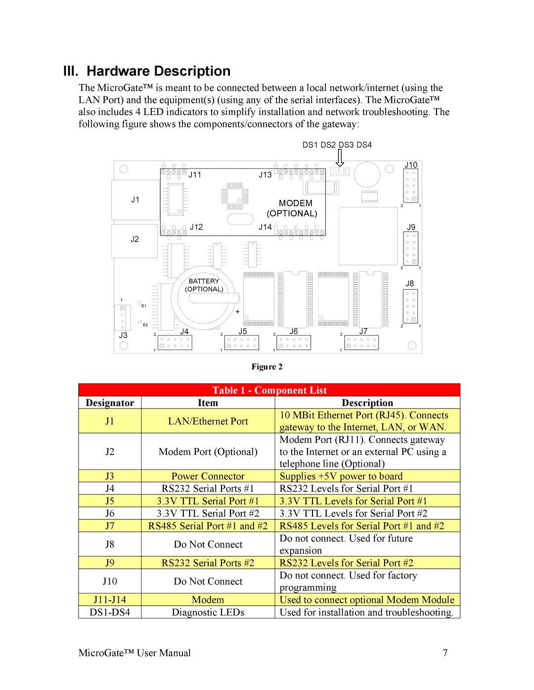
The MicroGate™ is meant to be connected between a local network/internet (using the LAN Port) and the equipment(s) (using any of the serial interfaces). The MicroGate™ also includes 4 LED indicators to simplify installation and network troubleshooting. The following figure shows the components/connectors of the gateway:
J1
J2
1
E1
E2
J3 2
DS1 DS2 DS3 DS4
| J10 |
J11 | J13 |
|
|
| MODEM |
|
| 2 | 1 |
|
|
| (OPTIONAL) |
|
|
|
|
J12 |
|
| J14 |
|
|
| J9 |
|
|
|
|
|
| 2 | 1 |
BATTERY |
|
|
|
|
|
| J8 |
(OPTIONAL) |
|
|
|
|
|
| |
|
| + |
|
|
|
|
|
J4 |
| J5 | 2 J6 |
| J7 | 2 | 1 |
2 | 2 |
|
| ||||
|
|
| 1 | 1 | 1 | 1 |
| |
|
|
|
| Figure 2 | ||||
|
|
|
|
|
|
|
| |
|
|
|
| Table 1 - Component List | ||||
| Designator |
| Item |
|
| Description | ||
| J1 |
|
| LAN/Ethernet Port |
|
| 10 MBit Ethernet Port (RJ45). Connects |
|
|
|
|
|
| gateway to the Internet, LAN, or WAN. |
| ||
|
|
|
|
|
|
|
| |
|
|
|
|
|
| Modem Port (RJ11). Connects gateway | ||
| J2 |
| Modem Port (Optional) |
| to the Internet or an external PC using a | |||
|
|
|
|
|
| telephone line (Optional) | ||
| J3 |
| Power Connector |
| Supplies +5V power to board | |||
| J4 |
| RS232 Serial Ports #1 |
| RS232 Levels for Serial Port #1 | |||
| J5 |
|
| 3.3V TTL Serial Port #1 |
|
| 3.3V TTL Levels for Serial Port #1 |
|
| J6 |
| 3.3V TTL Serial Port #2 |
|
| 3.3V TTL Levels for Serial Port #2 | ||
| J7 | RS485 Serial Port #1 and #2 |
| RS485 Levels for Serial Port #1 and #2 | ||||
| J8 |
| Do Not Connect |
| Do not connect. Used for future | |||
|
|
| expansion | |||||
|
|
|
|
|
| |||
| J9 |
| RS232 Serial Ports #2 |
| RS232 Levels for Serial Port #2 | |||
| J10 |
| Do Not Connect |
| Do not connect. Used for factory | |||
|
|
| programming | |||||
|
|
|
|
|
| |||
|
|
| Modem |
|
| Used to connect optional Modem Module |
| |
|
| Diagnostic LEDs |
| Used for installation and troubleshooting. | ||||
MicroGate™ User Manual | 7 |