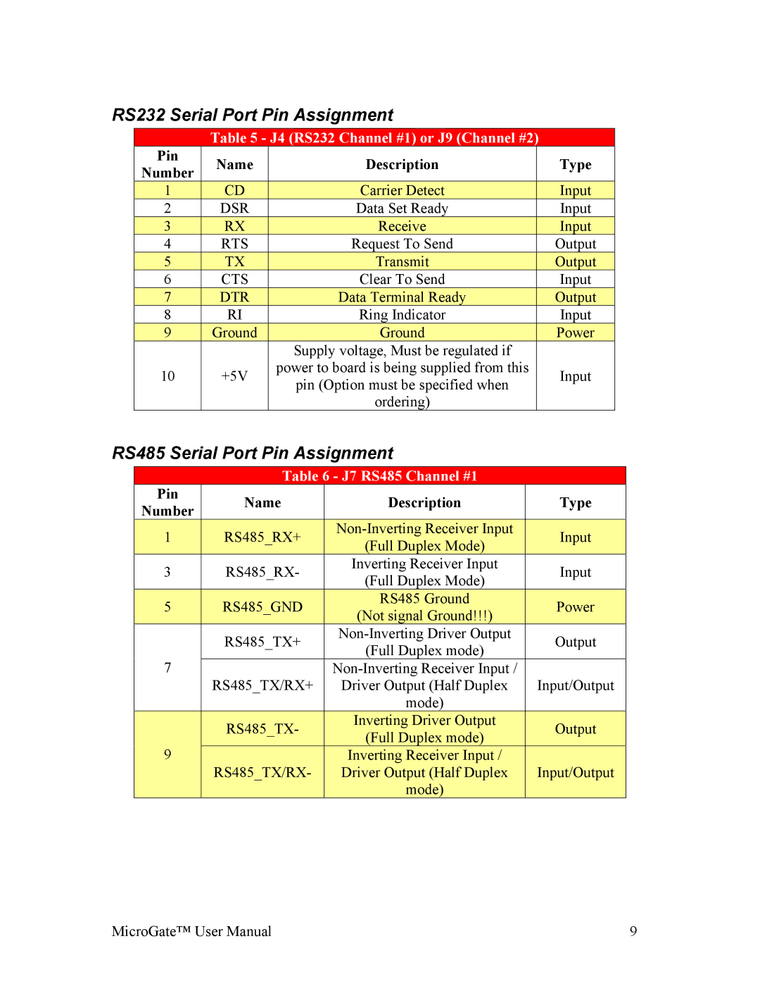
RS232 Serial Port Pin Assignment
Table 5 - J4 (RS232 Channel #1) or J9 (Channel #2)
| Pin |
| Name |
| Description |
| Type | |
| Number |
|
|
| ||||
|
|
|
|
|
|
| ||
1 |
|
| CD |
| Carrier Detect |
| Input | |
2 |
|
| DSR |
| Data Set Ready |
| Input | |
3 |
|
| RX |
| Receive |
| Input | |
4 |
|
| RTS |
| Request To Send |
| Output | |
| 5 |
|
| TX |
| Transmit |
| Output |
6 |
|
| CTS |
| Clear To Send |
| Input | |
7 |
|
| DTR |
| Data Terminal Ready |
| Output | |
8 |
|
| RI |
| Ring Indicator |
| Input | |
| 9 |
|
| Ground |
| Ground |
| Power |
|
|
|
|
|
| Supply voltage, Must be regulated if |
|
|
10 |
|
| +5V |
| power to board is being supplied from this |
| Input | |
|
|
| pin (Option must be specified when |
| ||||
|
|
|
|
|
|
|
| |
|
|
|
|
|
| ordering) |
|
|
RS485 Serial Port Pin Assignment
Table 6 - J7 RS485 Channel #1
| Pin |
| Name |
| Description | Type | |||
| Number |
|
| ||||||
|
|
|
|
|
|
|
| ||
| 1 |
|
| RS485_RX+ |
|
|
| Input | |
|
|
|
|
| (Full Duplex Mode) |
| |||
|
|
|
|
|
|
|
|
| |
3 |
|
| RS485_RX- |
| Inverting Receiver Input | Input | |||
|
|
| (Full Duplex Mode) | ||||||
|
|
|
|
|
|
|
| ||
| 5 |
|
| RS485_GND |
|
| RS485 Ground |
| Power |
|
|
|
|
| (Not signal Ground!!!) |
| |||
|
|
|
|
|
|
|
|
| |
|
|
|
| RS485_TX+ |
| Output | |||
|
|
|
|
| (Full Duplex mode) | ||||
7 |
|
|
|
|
|
| |||
|
|
|
|
|
| ||||
|
|
|
| RS485_TX/RX+ |
| Driver Output (Half Duplex | Input/Output | ||
|
|
|
|
|
|
| mode) |
| |
|
|
|
| RS485_TX- |
|
| Inverting Driver Output | Output | |
|
|
|
|
|
| (Full Duplex mode) | |||
| 9 |
|
|
|
|
|
| ||
|
|
|
|
|
| Inverting Receiver Input / |
| ||
|
|
|
| RS485_TX/RX- |
|
| Driver Output (Half Duplex | Input/Output | |
|
|
|
|
|
|
| mode) |
| |
MicroGate™ User Manual | 9 |