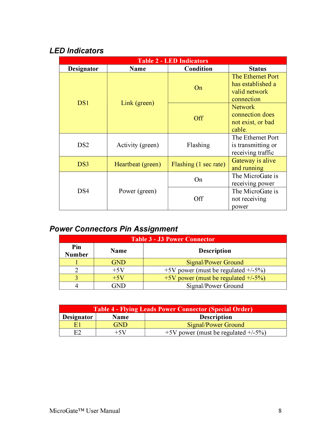
LED Indicators
Table 2 - LED Indicators
| Designator |
| Name |
| Condition |
| Status | ||||
|
|
|
|
|
|
|
|
|
| The Ethernet Port |
|
|
|
|
|
|
|
| On |
|
| has established a |
|
|
|
|
|
|
|
|
|
| valid network |
| |
|
|
|
|
|
|
|
|
|
|
| |
| DS1 |
|
| Link (green) |
|
|
|
|
| connection |
|
|
|
|
|
|
|
|
| Network |
| ||
|
|
|
|
|
|
|
|
|
|
| |
|
|
|
|
|
|
| Off |
|
| connection does |
|
|
|
|
|
|
|
|
|
| not exist, or bad |
| |
|
|
|
|
|
|
|
|
|
|
| |
|
|
|
|
|
|
|
|
|
| cable. |
|
|
|
|
|
|
|
|
|
|
| The Ethernet Port | |
| DS2 |
| Activity (green) |
| Flashing |
| is transmitting or | ||||
|
|
|
|
|
|
|
|
|
| receiving traffic | |
| DS3 |
|
| Heartbeat (green) |
|
| Flashing (1 sec rate) |
|
| Gateway is alive |
|
|
|
|
|
|
|
| and running |
| |||
|
|
|
|
|
|
|
|
|
|
| |
|
|
|
|
|
|
| On |
| The MicroGate is | ||
|
|
|
|
|
|
|
| receiving power | |||
| DS4 |
| Power (green) |
|
|
|
| ||||
|
|
|
|
|
| The MicroGate is | |||||
|
|
|
|
|
|
| Off |
| not receiving | ||
|
|
|
|
|
|
|
|
|
| power | |
Power Connectors Pin Assignment
|
|
|
| Table 3 - J3 Power Connector | ||
| Pin |
| Name |
|
| Description |
| Number |
|
|
| ||
|
|
|
|
|
| |
| 1 |
| GND |
|
| Signal/Power Ground |
2 |
| +5V |
|
| +5V power (must be regulated | |
| 3 |
| +5V |
|
| +5V power (must be regulated |
4 |
| GND |
|
| Signal/Power Ground | |
Table 4 - Flying Leads Power Connector (Special Order)
Designator | Name | Description |
E1 | GND | Signal/Power Ground |
E2 | +5V | +5V power (must be regulated |
MicroGate™ User Manual | 8 |