Open the RO water faucet until the tank is empty and flow stops.

Care and cleaning of the reverse osmosis system

Safety Instructions

Operating Instructions

Check valve tee

1/4tubing

Screen

Compression

nut

Flow control

Drain elbow

Flow Control and Screen

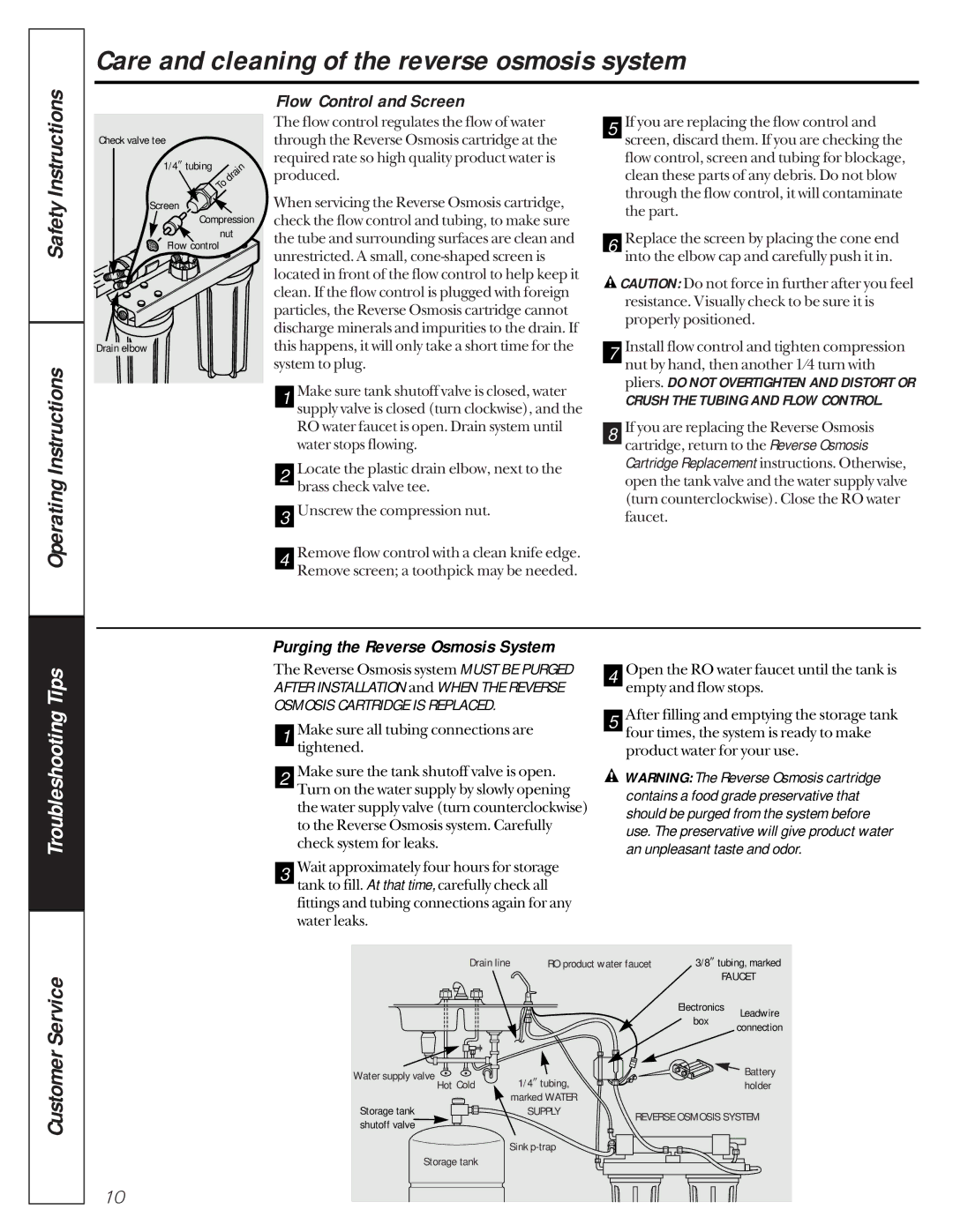
The flow control regulates the flow of water through the Reverse Osmosis cartridge at the required rate so high quality product water is produced.

When servicing the Reverse Osmosis cartridge, check the flow control and tubing, to make sure the tube and surrounding surfaces are clean and unrestricted. A small, cone-shaped screen is located in front of the flow control to help keep it clean. If the flow control is plugged with foreign particles, the Reverse Osmosis cartridge cannot discharge minerals and impurities to the drain. If this happens, it will only take a short time for the system to plug.


Make sure tank shutoff valve is closed, water

1


supply valve is closed (turn clockwise), and the


RO water faucet is open. Drain system until


water stops flowing.


Locate the plastic drain elbow, next to the

2


brass check valve tee.


Unscrew the compression nut.

3


Remove flow control with a clean knife edge.

4


Remove screen; a toothpick may be needed.

5 If you are replacing the flow control and screen, discard them. If you are checking the flow control, screen and tubing for blockage, clean these parts of any debris. Do not blow through the flow control, it will contaminate the part.

6 Replace the screen by placing the cone end into the elbow cap and carefully push it in.

CAUTION: Do not force in further after you feel resistance. Visually check to be sure it is properly positioned.

7 Install flow control and tighten compression nut by hand, then another 1⁄4 turn with pliers. DO NOT OVERTIGHTEN AND DISTORT OR

CRUSH THE TUBING AND FLOW CONTROL.

8 If you are replacing the Reverse Osmosis cartridge, return to the Reverse Osmosis Cartridge Replacement instructions. Otherwise, open the tank valve and the water supply valve (turn counterclockwise). Close the RO water faucet.

Troubleshooting Tips

Purging the Reverse Osmosis System

The Reverse Osmosis system MUST BE PURGED AFTER INSTALLATION and WHEN THE REVERSE OSMOSIS CARTRIDGE IS REPLACED.

1 Make sure all tubing connections are tightened.

2 Make sure the tank shutoff valve is open. Turn on the water supply by slowly opening the water supply valve (turn counterclockwise) to the Reverse Osmosis system. Carefully check system for leaks.

3 Wait approximately four hours for storage tank to fill. At that time, carefully check all fittings and tubing connections again for any water leaks.

4

5 After filling and emptying the storage tank four times, the system is ready to make product water for your use.

WARNING: The Reverse Osmosis cartridge

contains a food grade preservative that should be purged from the system before use. The preservative will give product water an unpleasant taste and odor.

Customer Service

Drain line

RO product water faucet

3/8tubing, marked


FAUCET


Electronics

Leadwire


box


connection


Water supply valve

1/4tubing,


Battery

Hot Cold


holder

Storage tank

marked WATER


SUPPLY

REVERSE OSMOSIS SYSTEM

shutoff valve


Sink p-trap


Storage tank


10

Page 10
Image 10
GE 215c1002p004-4 owner manual Flow Control and Screen, Purging the Reverse Osmosis System

215c1002p004-4 specifications

The GE 215C1002P004-4 is a high-performance electronic device that has gained prominence in various industrial and commercial applications. This component is part of General Electric's line of advanced technologies, reflecting the company's ongoing commitment to innovation and reliability.

One of the key features of the GE 215C1002P004-4 is its robust design, which allows it to operate efficiently in demanding environments. The device is engineered to withstand extreme temperatures and harsh conditions, ensuring longevity and dependable performance. This ruggedness makes it suitable for use in sectors such as manufacturing, aerospace, and energy.

In terms of technology, the GE 215C1002P004-4 boasts cutting-edge features that enhance its functionality. It incorporates advanced circuitry that enables precise control and monitoring capabilities. This is crucial for applications where accuracy is paramount, such as in industrial automation systems. The device also supports various communication protocols, making it versatile and compatible with a wide range of existing systems.

Another significant characteristic of the GE 215C1002P004-4 is its energy efficiency. As industries worldwide strive to reduce their carbon footprint and operational costs, the energy-efficient design of this device makes it an attractive option. It optimizes power consumption while maintaining high performance levels, aligning with modern sustainability goals.

The user interface of the GE 215C1002P004-4 is designed to be intuitive, facilitating easy operation and monitoring. This ease of use is crucial for technicians and operators who need to access real-time data and diagnostics to ensure optimal performance and quick troubleshooting.

Furthermore, the GE 215C1002P004-4 is compliant with various industry standards, ensuring that it meets rigorous safety and quality requirements. This compliance reinforces its reliability and bolsters customer confidence in its performance.

In conclusion, the GE 215C1002P004-4 is a versatile and efficient electronic device that stands out due to its rugged design, advanced technology, energy efficiency, and user-friendly interface. As industries continue to evolve, components like the GE 215C1002P004-4 play a vital role in driving innovation and improving operational efficiency across various sectors. Whether used in automation, control systems, or other applications, it exemplifies the quality and reliability that General Electric is known for.