EPM 3000P specifications
The GE EPM 3000P is a cutting-edge power monitoring and management device designed to enhance the reliability and efficiency of electrical systems. This innovative product combines advanced technology with user-friendly features to meet the growing demands of modern industrial and commercial environments.One of the standout features of the EPM 3000P is its ability to provide real-time monitoring of key electrical parameters. This includes voltage, current, power, energy consumption, and power factor, all displayed on a high-resolution graphical LCD screen. The device supports a wide range of communication protocols, allowing for seamless integration into existing systems. It is compatible with Modbus, Ethernet/IP, and DNP3, enabling users to communicate and collect data from remote locations efficiently.
Another significant aspect of the EPM 3000P is its robust data logging capabilities. The device can store extensive historical data, which can be easily accessed for analysis and reporting. This feature is essential for identifying trends, diagnosing issues, and ensuring compliance with energy regulations. Customizable alarms and notifications further enhance its functionality, alerting users to potential issues before they develop into costly problems.
The EPM 3000P also emphasizes safety and protection for electrical systems. It is equipped with advanced protection features, including overvoltage, undervoltage, overcurrent, and phase loss detection. This ensures that equipment is safeguarded against electrical faults, reducing the risk of damage and downtime.
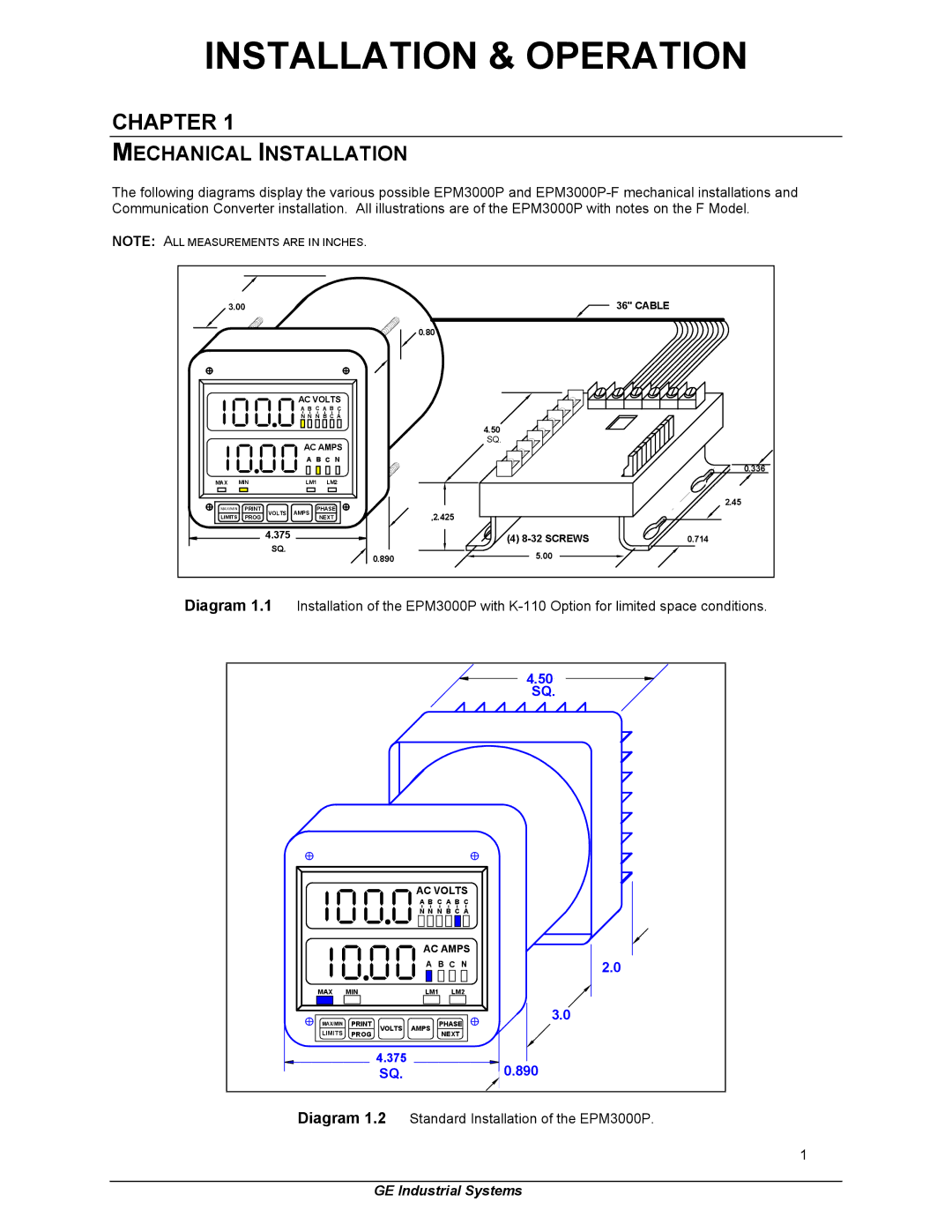
In terms of design, the EPM 3000P is both compact and rugged, making it suitable for installation in various environments. Its modular design allows for easy integration with other devices and systems, promoting scalability and future growth. The device is also compliant with international safety standards, ensuring reliability and peace of mind for users.
In conclusion, the GE EPM 3000P is a powerful tool for power management, offering users unparalleled monitoring, protection, and data analysis capabilities. With its advanced features, robust communication options, and user-friendly interface, it is positioned as an ideal solution for organizations looking to optimize their energy usage and enhance the resilience of their electrical systems. This makes it a preferred choice for industries aiming to improve operational efficiency and achieve sustainable energy practices.

