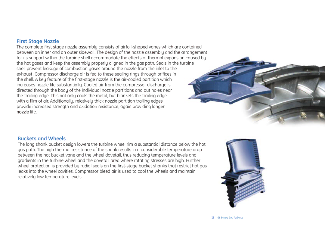
First Stage Nozzle
The complete first stage nozzle assembly consists of airfoil-shaped vanes which are contained between an inner and an outer sidewall. The design of the nozzle assembly and the arrangement for its support within the turbine shell accommodate the effects of thermal expansion caused by the hot gases and keep the assembly properly aligned in the gas path. Seals in the turbine shell prevent leakage of combustion gases around the nozzle from the inlet to the
exhaust. Compressor discharge air is fed to these sealing rings through orifices in the shell. A key feature of the first-stage nozzle is the air-cooled partition which increases nozzle life substantially. Cooled air from the compressor discharge is directed through the body of the individual nozzle partitions and out holes near the trailing edge. This not only cools the metal, but blankets the trailing edge with a film of air. Additionally, relatively thick nozzle partition trailing edges
provide increased strength and oxidation resistance, again providing longer nozzle life.
Buckets and Wheels
The long shank bucket design lowers the turbine wheel rim a substantial distance below the hot gas path. The high thermal resistance of the shank results in a considerable temperature drop between the hot bucket vane and the wheel dovetail, thus reducing temperature levels and gradients in the turbine wheel and the dovetail area where rotating stresses are high. Further wheel protection is provided by radial seals on the first-stage bucket shanks that restrict hot gas leaks into the wheel cavities. Compressor bleed air is used to cool the wheels and maintain relatively low temperature levels.
19GE Energy Gas Turbines