Manuals
/
GE
/
Kitchen Appliance
/
Water Dispenser
GE
GXSF27E
manual
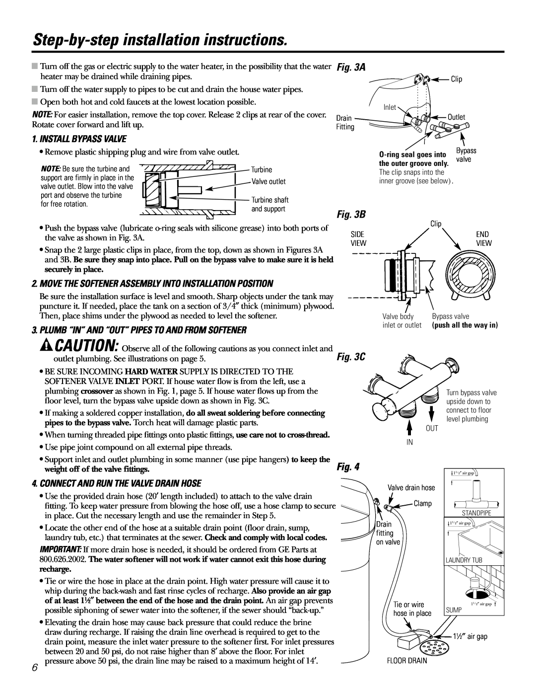
Step-by-stepinstallation instructions, Install Bypass Valve
Models:
GXSF27E
1
6
60
60
Download
60 pages
23.98 Kb
3
4
5
6
7
8
9
10
Troubleshooting
Specification
Install
Parts list
Error Signals
Señales De Error
Dimension
Problem
Parts and Accessories
How to
Page 6
Image 6
Page 5
Page 7
Page 6
Image 6
Page 5
Page 7
Contents
Water Softening System
Troubleshooting Tips
Water
Sistema Suavizante de Agua
SAFETY PRECAUTIONS
IMPORTANT SAFETY INFORMATION
READ ALL INSTRUCTIONS BEFORE USING
PROPER INSTALLATION
Installation instructions
Important Installation Recommendations
Unpacking and Inspection
Tools and Materials Required for Installation
Plan How You Will Install the Softener
Where to Install the Softener
Keep the softener out of direct sunlight
WATER
Typical Installation Illustration
Optional 3-ValveBypass Installation Illustration
PIPE
4. CONNECT AND RUN THE VALVE DRAIN HOSE
Step-by-stepinstallation instructions
1. INSTALL BYPASS VALVE
Fig. 3B
9.CONNECT TO ELECTRICAL POWER
4A. CONNECTING A RIGID VALVE DRAIN TUBE
6. INSTALL GROUNDING CLAMP
Fig. 4A
SET WATER HARDNESS NUMBER
Programming the Control
SET PRESENT TIME OF DAY
SET RECHARGE STARTING TIME
SYSTEM/ELECTRONIC DIAGNOSTICS
Optional Control Settings
ERROR SIGNALS
SALT EFFICIENCY
Sanitizing Procedures
Specifications/Dimensions
Automatic Hard Water Bypass During Recharge
About the water softener system
Service
Fill
Cleaning the Nozzle and Venturi Assembly
Breaking a Salt Bridge
Do not overtighten the cap
Feature/Service Automatic Electronic Diagnostics
Feature Optional Recharge Controls
Feature Memory
Normal Operation, Control Displays
POSSIBLE DEFECT
To remove an error code 1. Unplug transformer
NO SOFT WATER
VISUAL CHECKS
OPENA NEARBY SOFT WATER FAUCET
For correct water softening system
About the water softener system
Care and cleaning of the water softening system
Cleaning Iron Out of the Water Softening System
Checking the Salt Storage Level and Refilling
Before you call for service…
NO SOFT WATER-MostCommon Problems
not using any salt
Problem
after installation of
system was installed
brown/yellow colored
water after installation
Salty tasting or
Brown/yellow
Page
Parts list
Page
Parts catalog
GENERAL ELECTRIC PARTS CATALOG
0111
Staple your receipt here
What Is Not Covered
For The Period Of We Will Replace
One Year
For service, call toll free
For The Period Of
We Will Replace
Page
Instrucciones para la operación
Información de seguridad
Instrucciones para la
Consejos para la solución
PRECAUCIONES DE SEGURIDAD
INFORMACIÓN IMPORTANTE DE SEGURIDAD
LEA TODAS LAS INSTRUCCIONES ANTES DEL USO
ADVERTENCIA No use con agua que
Desempacado e inspección
Instrucciones de instalación
ADVERTENCIA No use con
Recomendaciones importantes para la instalación
ADVERTENCIA Use solamente
Planifique la instalación del Descalcificador
Dónde instalar el Descalcificador
PRINCIPAL
Ilustración de instalación normal
AGUA
Válvula de bypass
Fig. 3B
Instrucciones de instalación paso por paso
Fig. 3A
Fig. 3C
DE LA VÁLVULA
9.CONECTE EL SUMINISTRO ELÉCTRICO
6.INSTALE LA ABRAZADERA DE TIERRA
8.AGREGUE AGUA Y SAL AL TANQUE DE SALMUERA
Reemplace la cubierta superior
AJUSTE EL NIVEL DE DUREZA DEL AGUA
Programación del control
AJUSTE LA HORA DEL DÍA
AJUSTE LA HORA DE INICIO DE RECARGA
DIAGNÓSTICO ELECTRÓNICO/DEL SISTEMA
SEÑALES DE ERROR
Ajustes opcionales de control
EFICIENCIA DE LA SAL
Especificaciones/Dimensiones
Procedimientos de desinfección
Llenado
Sobre el sistema de descalcificación de agua
Servicio
Lavado Regresivo
Sal Instrumento
Cómo romper un puente de sal
1″-2″ 2,54 cm-5,1cm
Nivel de agua
Junta Tapón de flujo
Tapa Sello del aro tórico Soporte del filtro
Filtro Tapón de flujo
Boquilla y Venturi
RECARGUE ESTA NOCHE
Operación normal, Pantalla de control
Función Memoria
RECARGO AHORA
VISUALIZADO
INSPECCIONES VISUALES
EL INTERRUPTOR
CORRECTO MUESTRA ESTADO DEL CICLO DE LA VÁLVULA
RECHARGE recargo
PRECAUCIÓN
NO HAY AGUA DESCALCIFICADA-Problemasmás comunes
Antes de llamar para solicitar servicio…
El agua se siente
A veces el agua
está dura
resbalosa después de la
aspecto café o amarillo
Un error de código
El agua sabe a sal o tiene
después de la instalación
Notas
Notas
Notas
Lista de partes
Page
Catálogo de partes
CATÁLOGO DE PARTES DE GENERAL ELECTRIC
CATÁLOGO DE PARTES DE GENERAL ELECTRIC
Lo que no está cubierto
Por el período de
Reemplazamos
Garante General Electric Company. Louisville, KY
Solicite una reparación
Soporte al Consumidor
Página Web de GE Appliances
Garantías ampliadas
Consumer Support
Schedule Service
Parts and Accessories
GE Appliances Website
Top
Page
Image
Contents