TO RAISE OR REMOVE COOK TOP
![]() Remove 4 burner caps and 4 burner heads
Remove 4 burner caps and 4 burner heads
![]() Remove 4 electrodes (pull up on the electrode while gently rotating at the same time) & disconnect electrode leads.
Remove 4 electrodes (pull up on the electrode while gently rotating at the same time) & disconnect electrode leads.
![]() Remove (12)
Remove (12)
![]() Disengage the 2 front clips using a flat screw driver and gently raise the top high enough for the prop rods to hold it upright.
Disengage the 2 front clips using a flat screw driver and gently raise the top high enough for the prop rods to hold it upright.
FOR REMOVAL:
Disengage the prop rods from the range slide panels
While raising the front of the cooktop, lower the rear of the cook top and shift the top left or right in order to disengage the hinge pins at the rear.
IMPORTANT COOK TOP REINSTALLATION NOTES:
Before lowering the top onto the front clips, feed the electrode leads through each opening in the cook top. Next be sure that the electrode clips are inserted into each of the orifice brackets (see illustration below). Line up the orifice brackets with the holes in the
When reinstalling the top, position the top to be the equivalent of 1/2 way lowered, before attempting to insert the top hinge pins into the corresponding slots on the
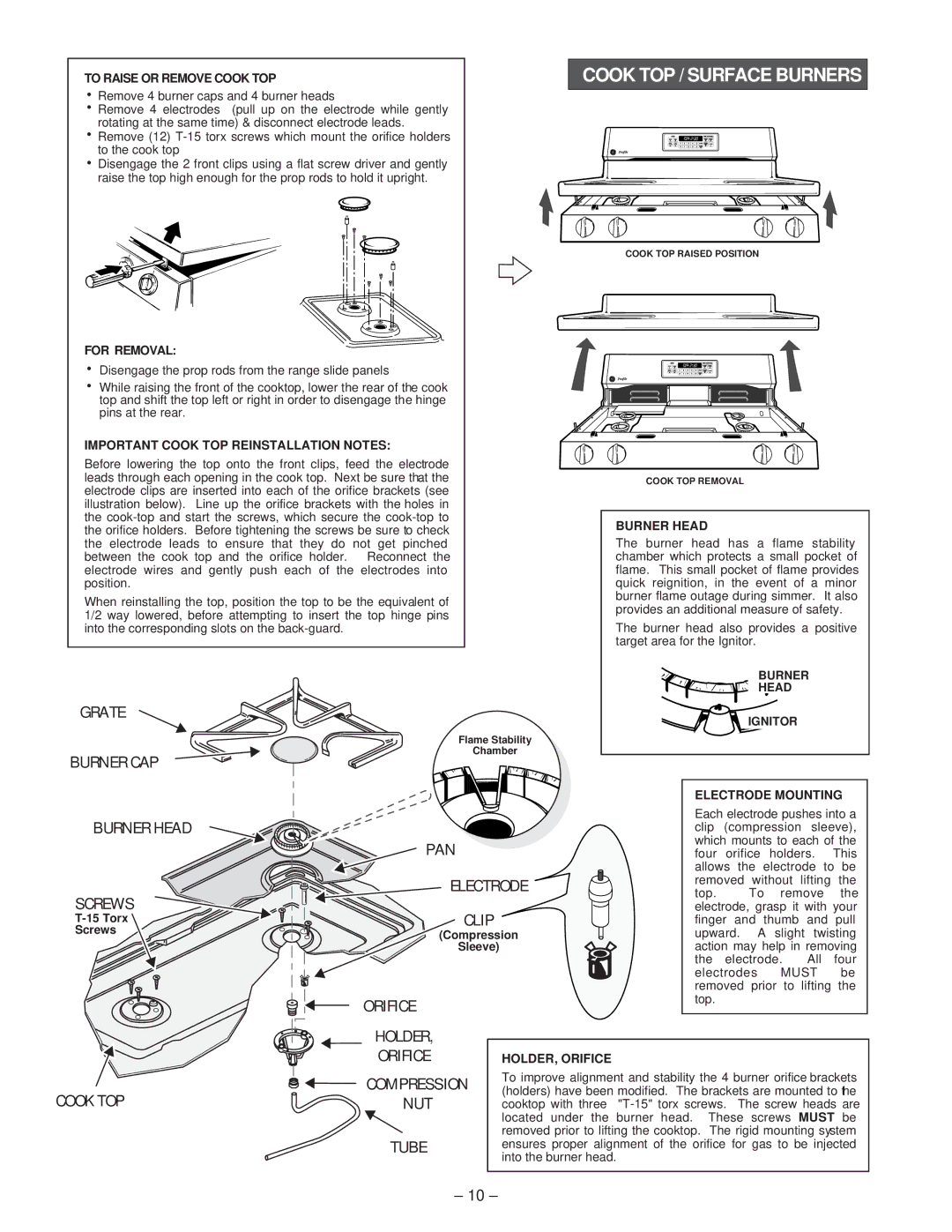
GRATE
Flame Stability
COOK TOP / SURFACE BURNERS
COOK TOP RAISED POSITION
COOK TOP REMOVAL
BURNER HEAD
The burner head has a flame stability chamber which protects a small pocket of flame. This small pocket of flame provides quick reignition, in the event of a minor burner flame outage during simmer. It also provides an additional measure of safety.
The burner head also provides a positive target area for the Ignitor.
BURNER
![]()
![]()
![]()
![]()
![]() HEAD
HEAD
![]()
![]() IGNITOR
IGNITOR
BURNER CAP
Chamber
ELECTRODE MOUNTING
BURNER HEAD |
| |
| PAN | |
SCREWS | ELECTRODE | |
CLIP | ||
Screws | (Compression | |
| Sleeve) | |
| ORIFICE |
Each electrode pushes into a clip (compression sleeve), which mounts to each of the four orifice holders. This allows the electrode to be removed without lifting the
top. To remove the electrode, grasp it with your finger and thumb and pull upward. A slight twisting action may help in removing
the electrode. All four electrodes MUST be removed prior to lifting the top.
| HOLDER, |
| ORIFICE |
COOK TOP | COMPRESSION |
NUT | |
| TUBE |
HOLDER, ORIFICE
To improve alignment and stability the 4 burner orifice brackets (holders) have been modified. The brackets are mounted to the cooktop with three
– 10 –