LOCK MOTOR CIRCUIT
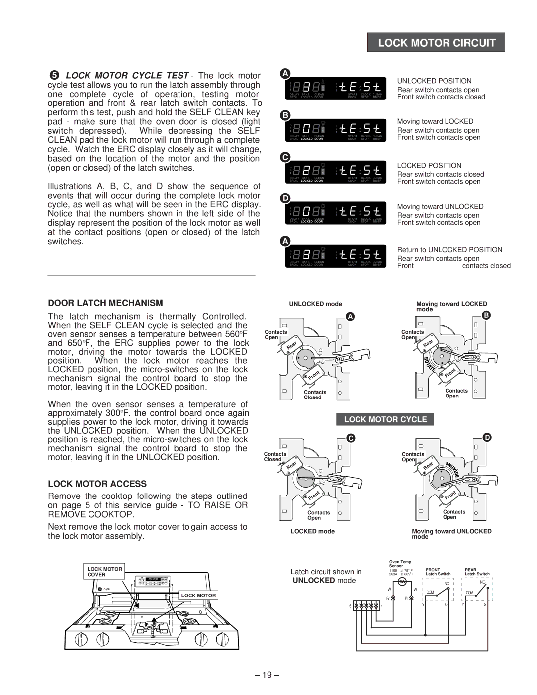
5LOCK MOTOR CYCLE TEST - The lock motor cycle test allows you to run the latch assembly through one complete cycle of operation, testing motor operation and front & rear latch switch contacts. To perform this test, push and hold the SELF CLEAN key pad - make sure that the oven door is closed (light switch depressed). While depressing the SELF CLEAN pad the lock motor will run through a complete cycle. Watch the ERC display closely as it will change, based on the location of the motor and the position (open or closed) of the latch switches.
Illustrations A, B, C, and D show the sequence of events that will occur during the complete lock motor cycle, as well as what will be seen in the ERC display. Notice that the numbers shown in the left side of the display represent the position of the lock motor as well at the contact positions (open or closed) of the latch switches.
DOOR LATCH MECHANISM
The latch mechanism is thermally Controlled. When the SELF CLEAN cycle is selected and the oven sensor senses a temperature between 560°F and 650°F, the ERC supplies power to the lock motor, driving the motor towards the LOCKED position. When the lock motor reaches the LOCKED position, the
A
S |
|
| S |
|
|
E |
| O | E |
|
|
T |
| N | T |
|
|
DELAY | BAKE | CLEAN | START | CLOCK | CLEAN |
BROIL | LOCKED | DOOR | COOK | STOP | TIMER |
B
S |
|
| S |
|
|
E |
| O | E |
|
|
T |
| N | T |
|
|
DELAY | BAKE | CLEAN | START | CLOCK | CLEAN |
BROIL | LOCKED | DOOR | COOK | STOP | TIMER |
C
S |
|
| S |
|
|
E |
| O | E |
|
|
T |
| N | T |
|
|
DELAY | BAKE | CLEAN | START | CLOCK | CLEAN |
BROIL | LOCKED | DOOR | COOK | STOP | TIMER |
D
S |
|
| S |
|
|
E |
| O | E |
|
|
T |
| N | T |
|
|
DELAY | BAKE | CLEAN | START | CLOCK | CLEAN |
BROIL | LOCKED | DOOR | COOK | STOP | TIMER |
A
S |
|
| S |
|
|
E |
| O | E |
|
|
T |
| N | T |
|
|
DELAY | BAKE | CLEAN | START | CLOCK | CLEAN |
BROIL | LOCKED | DOOR | COOK | STOP | TIMER |
UNLOCKED mode
A
Contacts
Open
![]() Rear
Rear ![]()
![]() Front
Front
Contacts
Closed
UNLOCKED POSITION
Rear switch contacts open Front switch contacts closed
Moving toward LOCKED
Rear switch contacts open
Front switch contacts open
LOCKED POSITION
Rear switch contacts closed Front switch contacts open
Moving toward UNLOCKED
Rear switch contacts open Front switch contacts open
Return to UNLOCKED POSITION Rear switch contacts open
Front | contacts closed |
Moving toward LOCKED mode
B
Contacts
Open
Rear ![]()
Front
Contacts
Open
When the oven sensor senses a temperature of approximately 300°F. the control board once again supplies power to the lock motor, driving it towards the UNLOCKED position. When the UNLOCKED position is reached, the
Contacts
Closed
![]() Rear
Rear ![]()
LOCK MOTOR CYCLE
C | D |
| Contacts |
| Open |
| Rear |
LOCK MOTOR ACCESS
Remove the cooktop following the steps outlined on page 5 of this service guide - TO RAISE OR REMOVE COOKTOP.
Next remove the lock motor cover to gain access to the lock motor assembly.
![]() Front
Front
Contacts
Open
LOCKED mode
Front
Contacts
Open
Moving toward UNLOCKED mode
LOCK MOTOR
COVER
LOCK MOTOR |
Oven Temp.
Sensor
Latch circuit shown in |
| 2634Ω at 865o | F. | |
|
| 1100Ω at 75o | F. | |
UNLOCKED mode |
|
|
|
|
| W |
| W | |
| F2 | F1 |
|
|
5 | 1 |
|
| Y |
|
|
| ||
FRONT |
| REAR |
Latch Switch |
| Latch Switch |
NC |
| NO |
COM |
| COM |
O | Y | S |
– 19 –