Instructions

Installation of the downdraft system. Read these instructions completely and carefully.

Step 3 is for 36 wide models only. Skip this step if installing a 30model.

Troubleshooting Tips Installation Instructions Operating Instructions Safety

Customer Service

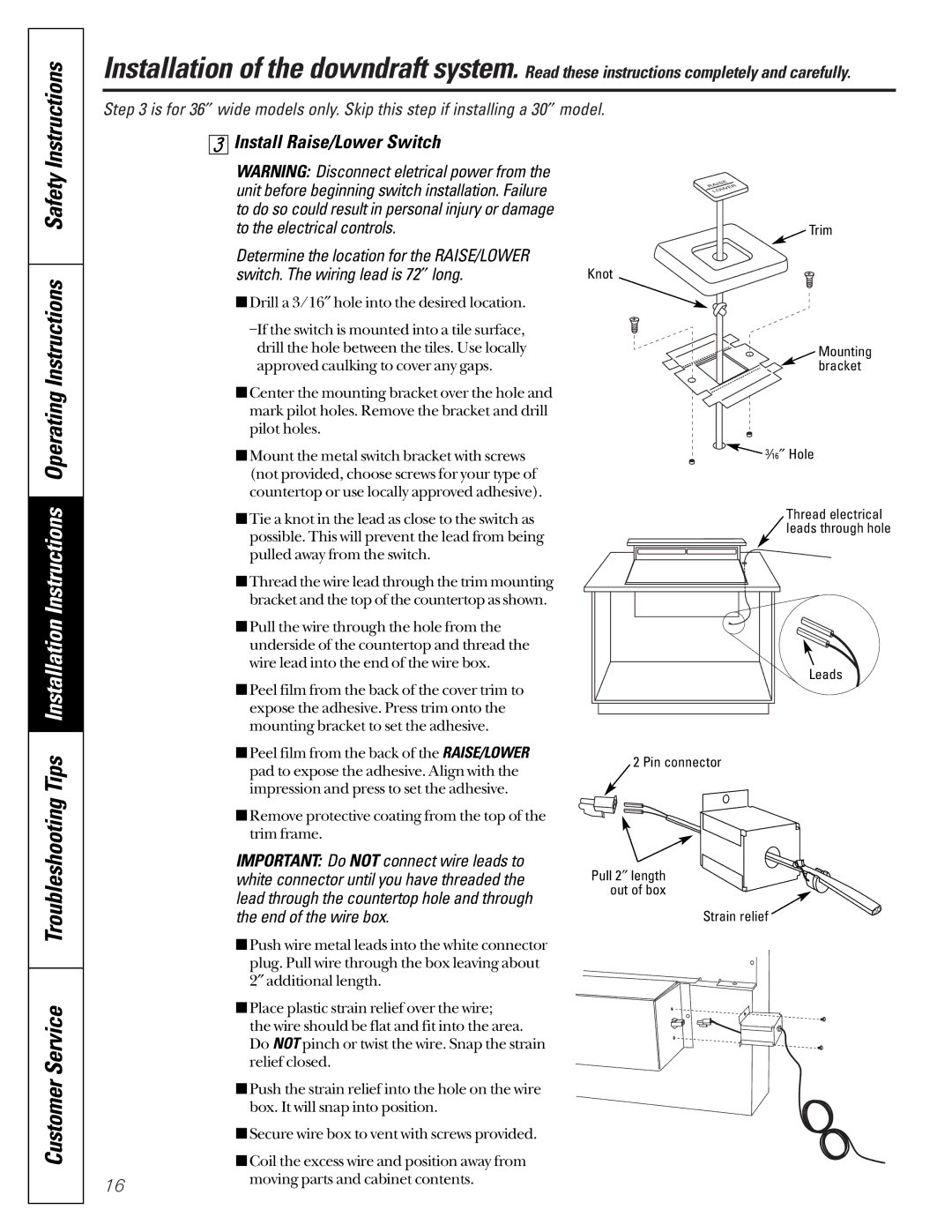
Install Raise/Lower Switch

WARNING: Disconnect eletrical power from the unit before beginning switch installation. Failure to do so could result in personal injury or damage to the electrical controls.

Determine the location for the RAISE/LOWER switch. The wiring lead is 72long.

Drill a 3/16″ hole into the desired location.

–If the switch is mounted into a tile surface, drill the hole between the tiles. Use locally approved caulking to cover any gaps.

Center the mounting bracket over the hole and mark pilot holes. Remove the bracket and drill pilot holes.

Mount the metal switch bracket with screws (not provided, choose screws for your type of countertop or use locally approved adhesive).

Tie a knot in the lead as close to the switch as possible. This will prevent the lead from being pulled away from the switch.

Thread the wire lead through the trim mounting bracket and the top of the countertop as shown.

Pull the wire through the hole from the underside of the countertop and thread the wire lead into the end of the wire box.

Peel film from the back of the cover trim to expose the adhesive. Press trim onto the mounting bracket to set the adhesive.

Peel film from the back of the RAISE/LOWER pad to expose the adhesive. Align with the impression and press to set the adhesive.

Remove protective coating from the top of the trim frame.

IMPORTANT: Do NOT connect wire leads to white connector until you have threaded the lead through the countertop hole and through the end of the wire box.

Push wire metal leads into the white connector plug. Pull wire through the box leaving about 2″ additional length.

Place plastic strain relief over the wire; the wire should be flat and fit into the area.

Do NOT pinch or twist the wire. Snap the strain relief closed.

Push the strain relief into the hole on the wire


box. It will snap into position.


Secure wire box to vent with screws provided.


Coil the excess wire and position away from

16

moving parts and cabinet contents.


Trim

Knot

Mounting bracket

316Hole

Thread electrical leads through hole

Leads

2 Pin connector

Pull 2length out of box

Strain relief

Page 16
Image 16
GE JVB67, JVB37 owner manual Install Raise/Lower Switch

JVB37, JVB67 specifications

The GE JVB37 and JVB67 are advanced connected commercial water heaters designed to meet the challenges of modern facilities while prioritizing efficiency, safety, and reliability. With an acute emphasis on smart technology, these models provide user-friendly features and robust performance for various applications, including restaurants, hotels, and multi-family buildings.

One of the standout features of the GE JVB37 and JVB67 is their energy efficiency. Both models utilize a state-of-the-art heat pump technology, which allows them to consume significantly less energy compared to traditional electric or gas-fired water heaters. This results in lower operating costs and a reduced environmental footprint, making them ideal choices for businesses looking to enhance their sustainability efforts.

The JVB37 has a 37-gallon capacity, while the JVB67 offers a larger 67-gallon capacity, catering to different usage requirements. These models are equipped with an intuitive digital interface that provides real-time monitoring and control, ensuring users can easily adjust the temperature settings and monitor energy consumption. Moreover, the connectivity features enable remote management through mobile apps or smart devices, providing added convenience for facility managers.

In terms of safety, both models incorporate advanced features such as leak detection, automatic shut-off valves, and tamper-proof designs. These safeguards help prevent potential hazards while ensuring a reliable supply of hot water. Furthermore, the build quality of the JVB37 and JVB67 reflects GE's commitment to longevity, with durable materials that resist corrosion and wear, ensuring years of dependable service.

The installation of the JVB37 and JVB67 is simplified due to their compact designs, allowing for flexibility in various settings. Whether mounted on the wall or positioned in tight spaces, these water heaters can adapt to different layouts without compromising performance.

Overall, the GE JVB37 and JVB67 are exemplary models in the market of connected commercial water heaters, seamlessly blending innovation with practicality. Their energy-efficient operation, combined with smart technologies and robust safety features, makes them ideal solutions for businesses aiming to optimize their hot water needs while prioritizing sustainability and efficiency.