EDID MODES
EDID Modes
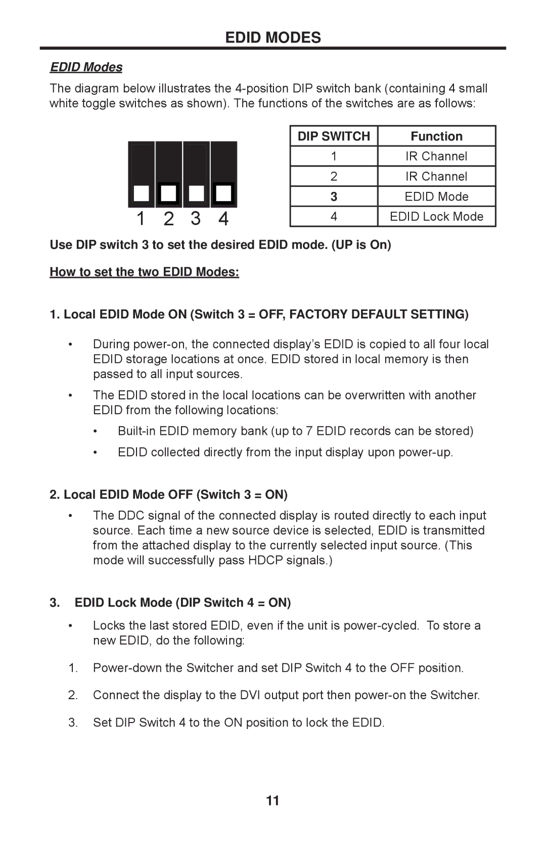
The diagram below illustrates the
1 | 2 | 3 | 4 |
DIP SWITCH | Function |
1 | IR Channel |
2 | IR Channel |
3 | EDID Mode |
4 | EDID Lock Mode |
Use DIP switch 3 to set the desired EDID mode. (UP is On) How to set the two EDID Modes:
1.Local EDID Mode ON (Switch 3 = OFF, FACTORY DEFAULT SETTING)
•During
•The EDID stored in the local locations can be overwritten with another EDID from the following locations:
•
•EDID collected directly from the input display upon
2.Local EDID Mode OFF (Switch 3 = ON)
•The DDC signal of the connected display is routed directly to each input source. Each time a new source device is selected, EDID is transmitted from the attached display to the currently selected input source. (This mode will successfully pass HDCP signals.)
3.EDID Lock Mode (DIP Switch 4 = ON)
•Locks the last stored EDID, even if the unit is
1.
2.Connect the display to the DVI output port then
3.Set DIP Switch 4 to the ON position to lock the EDID.
11
