Section 1 — Installation
Guardian
|
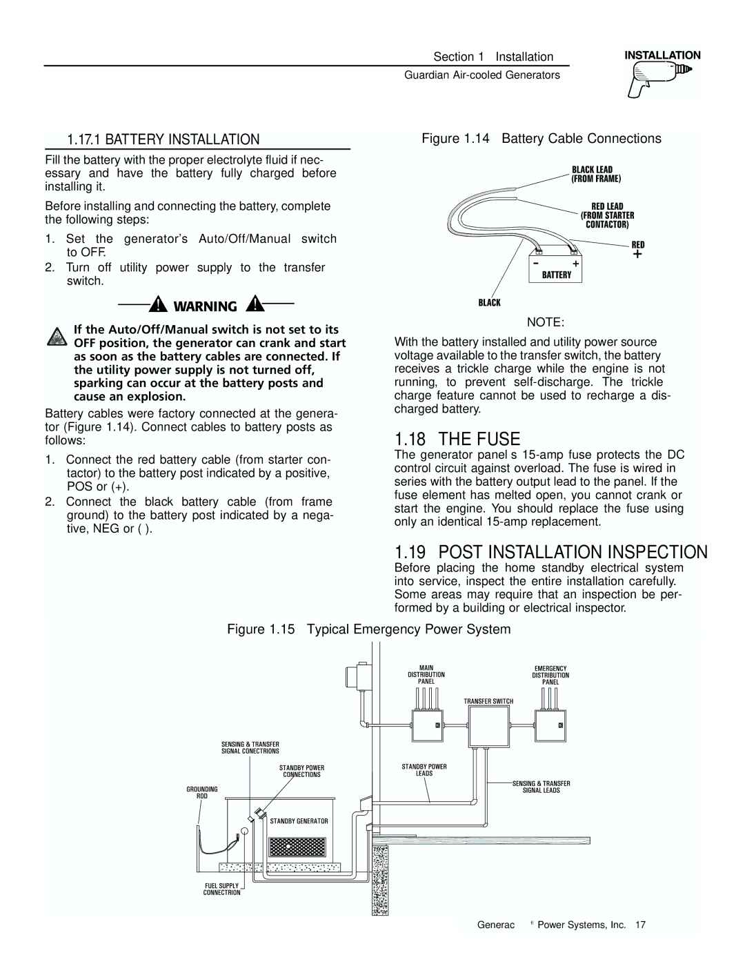
| 1.17.1 BATTERY INSTALLATION | Figure 1.14 – Battery Cable Connections |
| ◆ | ||
|
|
|
|
Fill the battery with the proper electrolyte fluid if nec- essary and have the battery fully charged before installing it.
Before installing and connecting the battery, complete the following steps:
1.Set the generator's Auto/Off/Manual switch to OFF.
2.Turn off utility power supply to the transfer switch.
If the Auto/Off/Manual switch is not set to its OFF position, the generator can crank and start as soon as the battery cables are connected. If the utility power supply is not turned off, sparking can occur at the battery posts and cause an explosion.
Battery cables were factory connected at the genera- tor (Figure 1.14). Connect cables to battery posts as follows:
1.Connect the red battery cable (from starter con- tactor) to the battery post indicated by a positive, POS or (+).
2.Connect the black battery cable (from frame ground) to the battery post indicated by a nega- tive, NEG or
NOTE:
With the battery installed and utility power source voltage available to the transfer switch, the battery receives a trickle charge while the engine is not running, to prevent
1.18 THE FUSE
The generator panel’s
1.19 POST INSTALLATION INSPECTION
Before placing the home standby electrical system into service, inspect the entire installation carefully. Some areas may require that an inspection be per- formed by a building or electrical inspector.
Figure 1.15 – Typical Emergency Power System
Generac® Power Systems, Inc. 17