Section 2 — Operation
2.5.3.1 Approximate Crank Cycle Times
•15 seconds ON
•15 seconds OFF
•7 seconds ON
•7 seconds OFF
•Repeat for 45 seconds Approximately 90 seconds total
Guardian
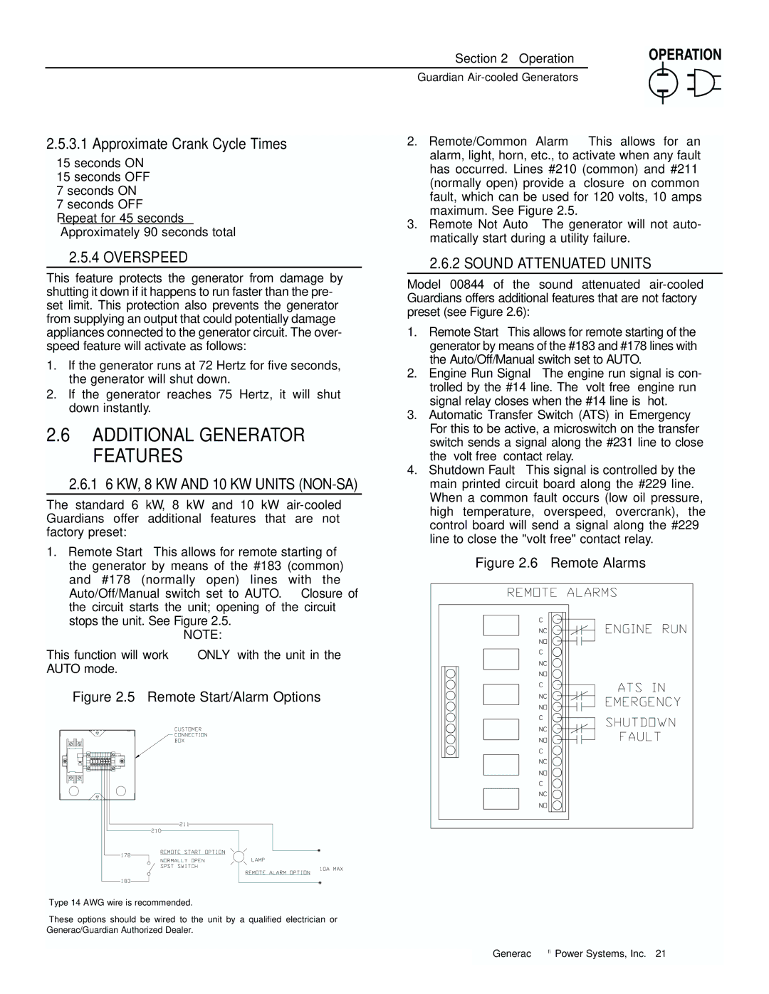
2.Remote/Common Alarm – This allows for an alarm, light, horn, etc., to activate when any fault has occurred. Lines #210 (common) and #211 (normally open) provide a “closure” on common fault, which can be used for 120 volts, 10 amps maximum. See Figure 2.5.
3.Remote Not Auto – The generator will not auto- matically start during a utility failure.
◆2.5.4 OVERSPEED
This feature protects the generator from damage by shutting it down if it happens to run faster than the pre- set limit. This protection also prevents the generator from supplying an output that could potentially damage appliances connected to the generator circuit. The over- speed feature will activate as follows:
1.If the generator runs at 72 Hertz for five seconds, the generator will shut down.
2.If the generator reaches 75 Hertz, it will shut down instantly.
2.6ADDITIONAL GENERATOR FEATURES
◆2.6.1 6 KW, 8 KW AND 10 KW UNITS (NON-SA)
The standard 6 kW, 8 kW and 10 kW
1.Remote Start – This allows for remote starting of the generator by means of the #183 (common) and #178 (normally open) lines with the Auto/Off/Manual switch set to AUTO. Closure of the circuit starts the unit; opening of the circuit stops the unit. See Figure 2.5.
NOTE:
This function will work ONLY with the unit in the AUTO mode.
Figure 2.5 – Remote Start/Alarm Options
◆2.6.2 SOUND ATTENUATED UNITS
Model 00844 of the sound attenuated
1.Remote Start – This allows for remote starting of the generator by means of the #183 and #178 lines with the Auto/Off/Manual switch set to AUTO.
2.Engine Run Signal – The engine run signal is con- trolled by the #14 line. The “volt free” engine run signal relay closes when the #14 line is “hot.”
3.Automatic Transfer Switch (ATS) in Emergency – For this to be active, a microswitch on the transfer switch sends a signal along the #231 line to close the “volt free” contact relay.
4.Shutdown Fault – This signal is controlled by the main printed circuit board along the #229 line. When a common fault occurs (low oil pressure, high temperature, overspeed, overcrank), the control board will send a signal along the #229 line to close the "volt free" contact relay.
Figure 2.6 – Remote Alarms
Generac® Power Systems, Inc. 21
