Section 3 - Operation
Guardian
CONTROL CONSOLE COMPONENTS
The components of a
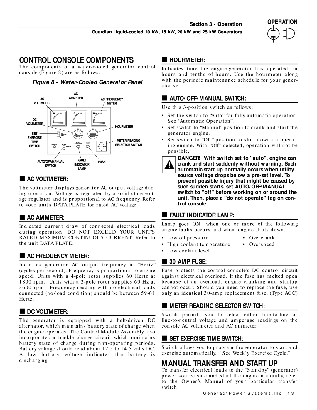
Figure 8 -
![]() HOURMETER:
HOURMETER:
Indicates time the
![]() AC VOLTMETER:
AC VOLTMETER:
The voltmeter displays generator AC output voltage dur- ing operation. Voltage is regulated by a solid state volt- age regulator and is proportional to AC frequency. Refer to your unit’s DATA PLATE for rated AC voltage.
![]() AUTO/OFF/MANUAL SWITCH:
AUTO/OFF/MANUAL SWITCH:
Use this
•Set the switch to “Auto” for fully automatic operation. See “Automatic Operation”.
•Set switch to “Manual” position to crank and start the generator engine.
•Set switch to “Off” position to shut down an operat- ing engine. With “Off” selected, operation will not be possible.
DANGER! With switch set to "auto", engine can crank and start suddenly without warning. Such automatic start up normally occurs when utility source voltage drops below a
![]() AC AMMETER:
AC AMMETER:
Indicated current draw of connected electrical loads during operation. DO NOT EXCEED YOUR UNIT’S RATED MAXIMUM CONTINUOUS CURRENT. Refer to the unit DATA PLATE.
![]() AC FREQUENCY METER:
AC FREQUENCY METER:
Indicates generator AC output frequency in “Hertz” (cycles per second). Frequency is proportional to engine speed. Units with a
![]() DC VOLTMETER:
DC VOLTMETER:
The generator is equipped with a
![]() FAULT INDICATOR LAMP:
FAULT INDICATOR LAMP:
Lamp goes ON when one or more of the following engine faults occurs and when engine shuts down.
• Low oil pressure | • | Overcrank |
• High coolant temperature | • | Overspeed |
• Low coolant level |
|
|
![]() 30 AMP FUSE:
30 AMP FUSE:
Fuse protects the control console’s DC control circuit against electrical overload. If the fuse has melted open because of an overload, engine cranking and startup cannot occur. Should you need to replace the fuse, use only an identical
![]() METER READING SELECTOR SWITCH:
METER READING SELECTOR SWITCH:
Switch permits you to select either
![]() SET EXERCISE TIME SWITCH:
SET EXERCISE TIME SWITCH:
Switch allows you to program the generator to start and exercise automatically. “See Weekly Exercise Cycle.”
MANUAL TRANSFER AND START UP
To transfer electrical loads to the “Standby” (generator) power source side and start the engine manually, refer to the Owner’s Manual of your particular transfer switch.
Generac® Power Systems, Inc. 13