ONLY QUALIFIED ELECTRICIANS OR CONTRACTORS
POWER SYSTEMS, INC
SHOULD ATTEMPT INSTALLATION
Liquid-cooled, Prepackaged Standby Generators
HOW TO OBTAIN SERVICE
AUTHORIZED SERVICE DEALER LOCATION
INTRODUCTION
OPERATION AND MAINTENANCE
INTRODUCTION
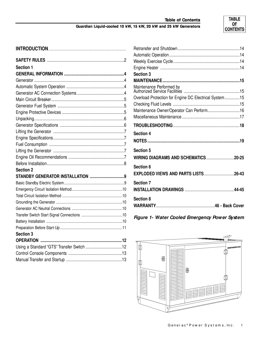
Figure 1- Water Cooled Emergency Power System
GENERAL HAZARDS
ELECTRICAL HAZARDS
FIRE HAZARDS
EXPLOSION HAZARDS
Figure 2 - Generator AC Connection System
GENERATOR
AUTOMATIC SYSTEM OPERATION
GENERATOR AC CONNECTION SYSTEMS
Figure 4 - Low Oil Pressure Switch
ENGINE PROTECTIVE DEVICES
MAIN CIRCUIT BREAKER
GENERATOR FUEL SYSTEM
Figure 7 - Control Module Assembly Circuit Board
SPECIFICATIONS
UNPACKING
LOW COOLANT LEVEL SWITCH
ENGINE OIL RECOMMENDATIONS
TORQUE SPECIFICATIONS
LIFTING THE GENERATOR
FUEL CONSUMPTION
8 Generac Power Systems, Inc
BEFORE INSTALLATION
OTHER PUBLISHED STANDARDS
STANDBY GENERATOR INSTALLATION
BASIC STANDBY ELECTRIC SYSTEM
NFPA STANDARDS
TOTAL CIRCUIT ISOLATION METHOD
TRANSFER SWITCH START SIGNAL CONNECTIONS
BATTERY INSTALLATION
EMERGENCY CIRCUIT ISOLATION METHOD
DO NOT cause flame or spark in battery area, and
PREPARATION BEFORE START-UP
Transfer Switch
DO NOT SMOKE when near batteries
Electrical System
USING A STANDARD “GTS” TRANSFER SWITCH
spill during system bleeding process. Clean up all
Generator Set Lubrication
MANUAL TRANSFER AND START UP
CONTROL CONSOLE COMPONENTS
ENGINE HEATER
RETRANSFER AND SHUTDOWN
AUTOMATIC OPERATION
WEEKLY EXERCISE CYCLE
Figure 11 - Oil Dipstick and Oil Fill Cap
CHECKING FLUID LEVELS
OVERLOAD PROTECTION FOR ENGINE DC ELECTRICAL SYSTEM
MAINTENANCE PERFORMED BY AUTHORIZED SERVICE FACILITIES
MAINTENANCE OWNER/OPERATOR CAN PERFORM
BATTERY REPLACEMENT
MISCELLANEOUS MAINTENANCE
CLEANING THE GENERATOR
BATTERY
CORRECTION
PERIODIC REPLACEMENT PARTS
PROBLEM
CAUSE
Guardian Liquid-cooled 10 kW, 15 kW, 20 kW and 25 kW Generators
Generac Power Systems, Inc
Guardian Liquid-cooled 10 kW, 15 kW, 20 kW and 25 kW Generators
Wiring Diagram - Control Panel 1-Phase -Drawing No. 0A2803C
20 Generac Power Systems, Inc
Section 6 - Electrical Data
Section 6 - Electrical Data
Generac Power Systems, Inc
22 Generac Power Systems, Inc
Section 6 - Electrical Data
Generac Power Systems, Inc
24 Generac Power Systems, Inc
Section 6 - Electrical Data
Generac Power Systems, Inc
Section 7 - Exploded Views and Parts
26 Generac Power Systems, Inc
DESCRIPTION
DESCRIPTION
A2110
Section 7 - Exploded Views and Parts
28 Generac Power Systems, Inc
DESCRIPTION
DECAL, TRANS. SWITCH CONN
SWITCH DPST 5 125V SPD RCKR
SWITCH DPDT 15/10 SP ON-OFF-ON
Section 7 - Exploded Views and Parts
30 Generac Power Systems, Inc
DESCRIPTION
DESCRIPTION
32 Generac Power Systems, Inc
DESCRIPTION
CIRCT BRK 35X2 W/39782 BRACKET
34 Generac Power Systems, Inc
DESCRIPTION
DESCRIPTION
BLOCK TERM 20A 7 X
DESCRIPTION
DESCRIPTION
SCREW CRIMPTITE 1/4-20 X 5/8
36 Generac Power Systems, Inc
PART NO.QTY
DESCRIPTION
DESCRIPTION
Section 7 - Exploded Views and Parts
38 Generac Power Systems, Inc
ASSY MPU SPEED SENSOR
DESCRIPTION
DESCRIPTION
SCREW HHC M10-1.25 X 20 G8.8
Section 7 - Exploded Views and Parts
40 Generac Power Systems, Inc
6-1/2
DESCRIPTION
Section 7 - Exploded Views and Parts
42 Generac Power Systems, Inc
0A45310258
DESCRIPTION
DESCRIPTION
PLUG STD PIPE 3/8 STEEL SQ HD
Guardian Liquid-cooled 10 kW, 15 kW, 20 kW and 25 kW Generators
Section 8 - Installation
Installation Drawing - Drawing No. 0C1450
44 Generac Power Systems, Inc
Guardian Liquid-cooled 10 kW, 15 kW, 20 kW and 25 kW Generators
Section 8 - Installation
Installation Drawing - Drawing No. 0C1450
Generac Power Systems, Inc
Guardian Liquid-cooled 10 kW, 15 kW, 20 kW and 25 kW Generators
46 Generac Power Systems, Inc
Guardian Liquid-cooled 10 kW, 15 kW, 20 kW and 25 kW Generators
Generac Power Systems, Inc
PURCHASER’S/OWNER’S WARRANTY RESPONSIBILITIES
CALIFORNIA EMISSION CONTROL WARRANTY STATEMENT
YOUR WARRANTY RIGHTS AND OBLIGATIONS
MANUFACTURER’S EMISSION CONTROL SYSTEM WARRANTY COVERAGE
EMISSION RELATED PARTS INCLUDE THE FOLLOWING
EMISSION CONTROL SYSTEM WARRANTY
WARRANTY SCHEDULE
GENERAC POWER SYSTEMS, INC
Rate Manual