Section 3 - Operation
QUIETSOURCE™
2.11.7 ELECTRICAL SYSTEM | NOTE: |
Make sure the generator is properly connected to an approved earth ground and/or ground rod.
Make sure the generator battery is fully charged, properly installed and interconnected, and ready for use.
Check to ensure that there are no loose electrical con- nections. Restrain any loose wires to keep them clear of any moving generator set components.
If the generator is installed in conjunction with an engineered GTS type transfer switch, refer to the applicable transfer switch manual for exact oper- ating parameters and timing sequences.
3.2CONTROL CONSOLE
COMPONENTS
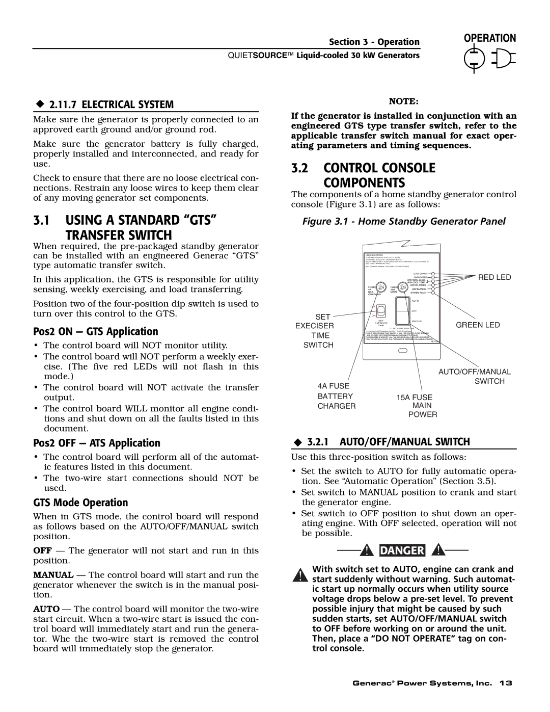
The components of a home standby generator control console (Figure 3.1) are as follows:
3.1USING A STANDARD “GTS”
TRANSFER SWITCH
Figure 3.1 - Home Standby Generator Panel
When required, the
In this application, the GTS is responsible for utility sensing, weekly exercising, and load transferring.
Position two of the
Pos2 ON — GTS Application
• The control board will NOT monitor utility. |
• The control board will NOT perform a weekly exer- |
cise. (The five red LEDs will not flash in this |
SET EXECISER TIME SWITCH
LED INDICATORS:
FLASHING GREEN LED = NO UTILITY SENSE
5 FLASHING RED LED'S = EXERCISER NOT SET
(IN AUTO MODE ONLY) SOLID GREEN LED = SYSTEM READY, UTILITY POWER ON RED LED'S = INDIVIDUAL FAULT
(SEE OWNER'S MANUAL FOR COMPLETE LED DETAILS)
|
| OVER CRANK | RED LED |
|
|
| |
SE |
| SE |
|
U | F | F U |
|
|
| AUTO |
|
OFF |
|
|
|
|
| OFF |
|
ON |
|
|
|
SET | MANUAL | GREEN LED | |
EXERCISE | TO SET EXERCISER TIME | ||
TIME
1) PLACE AUTO/OFF/MANUAL SWITCH TO AUTO POSITION.
0E7194
mode.) |
• The control board will NOT activate the transfer |
output. |
• The control board WILL monitor all engine condi- |
tions and shut down on all the faults listed in this |
document. |
Pos2 OFF — ATS Application
•The control board will perform all of the automat- ic features listed in this document.
•The
GTS Mode Operation
When in GTS mode, the control board will respond as follows based on the AUTO/OFF/MANUAL switch position.
OFF — The generator will not start and run in this position.
MANUAL — The control board will start and run the generator whenever the switch is in the manual posi- tion.
AUTO — The control board will monitor the
| AUTO/OFF/MANUAL |
4A FUSE | SWITCH |
| |
BATTERY | 15A FUSE |
CHARGER | MAIN |
| POWER |
3.2.1 AUTO/OFF/MANUAL SWITCH
Use this
•Set the switch to AUTO for fully automatic opera- tion. See “Automatic Operation” (Section 3.5).
•Set switch to MANUAL position to crank and start the generator engine.
•Set switch to OFF position to shut down an oper- ating engine. With OFF selected, operation will not be possible.
![]()
![]() DANGER
DANGER
With switch set to AUTO, engine can crank and
!start suddenly without warning. Such automat- ic start up normally occurs when utility source voltage drops below a
Generac® Power Systems, Inc. 13