Section 1 — General Information
QUIETSOURCE™
Figure 1.6 - Low Coolant Level Sensor | 1.7.7 LOW BATTERY |
1.7.4 OVERSPEED SHUTDOWN
The engine control board receives AC frequency sig- nals from an engine run winding in the alternator. Should AC frequency exceed about 72 Hertz for three seconds or 75 Hertz instantaniously, the engine shuts down and the overspeed LED turns on. Should AC frequency exceed about 72 Hertz, circuit board action will automatically shutdown the engine (Figure 1.7).
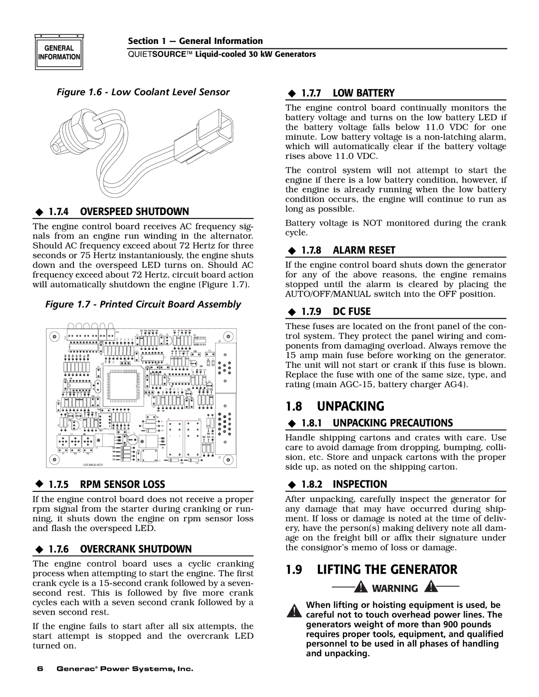
Figure 1.7 - Printed Circuit Board Assembly
| LED1 |
| R44 |
| C27 | Q2 | |
| C9 | ||
2 |
|
|
J2
C26
U7
C4
![]() D10
D10
|
| C21 |
C30 |
|
|
| C2 |
|
| RL1 | RL2 |
| R1 |
|
R25 | R48 |
|
| D17 |
|
R49 |
|
|
| U1 |
|
|
| J1 |
| L3 |
|
| .REV 0E4906 PCB# | D19 |
|
|
1.7.5 RPM SENSOR LOSS
If the engine control board does not receive a proper rpm signal from the starter during cranking or run- ning, it shuts down the engine on rpm sensor loss and flash the overspeed LED.
1.7.6 OVERCRANK SHUTDOWN
The engine control board uses a cyclic cranking process when attempting to start the engine. The first crank cycle is a
If the engine fails to start after all six attempts, the start attempt is stopped and the overcrank LED turned on.
The engine control board continually monitors the battery voltage and turns on the low battery LED if the battery voltage falls below 11.0 VDC for one minute. Low battery voltage is a
The control system will not attempt to start the engine if there is a low battery condition, however, if the engine is already running when the low battery condition occurs, the engine will continue to run as long as possible.
Battery voltage is NOT monitored during the crank cycle.
1.7.8 ALARM RESET
If the engine control board shuts down the generator for any of the above reasons, the engine remains stopped until the alarm is cleared by placing the AUTO/OFF/MANUAL switch into the OFF position.
1.7.9 DC FUSE
These fuses are located on the front panel of the con- trol system. They protect the panel wiring and com- ponents from damaging overload. Always remove the 15 amp main fuse before working on the generator. The unit will not start or crank if this fuse is blown. Replace the fuse with one of the same size, type, and rating (main
1.8UNPACKING
1.8.1 UNPACKING PRECAUTIONS
Handle shipping cartons and crates with care. Use care to avoid damage from dropping, bumping, colli- sion, etc. Store and unpack cartons with the proper side up, as noted on the shipping carton.
1.8.2 INSPECTION
After unpacking, carefully inspect the generator for any damage that may have occurred during ship- ment. If loss or damage is noted at the time of deliv- ery, have the person(s) making delivery note all dam- age on the freight bill or affix their signature under the consignor’s memo of loss or damage.
1.9LIFTING THE GENERATOR
When lifting or hoisting equipment is used, be
!careful not to touch overhead power lines. The generators weight of more than 900 pounds requires proper tools, equipment, and qualified personnel to be used in all phases of handling and unpacking.
6 Generac® Power Systems, Inc.