Integrated L-Band Up/Dn Converter LT3600

CG-1309


2.4.6 External 10 MHz Input (J2)

This connector is a BNC female. The male mate (not supplied) should be compatible with the 50-ohm coax used to connect to the system.

2.4.7 SSPB Interface (J6)

This connector is a 9-pin female miniature type “D” connector with standard #4-40 female screw-lock hardware mounting. The mating shell, pins, and strain relief are not supplied. Outputs are open collector and inputs have internal 1K full PS to +5V. The pin-out is as follows:

Pin 1 SSPB Band Control Output -

(Low = Lo Band)

Pin 2 Amplifier Fault - Open (Hi) = ALM Pin 3 Thermal Alarm Input –

Open (Hi) = ALM

Pin 4 Lock Alarm Input - Open (Hi) = ALM Pin 5 Up/Dn Converter Ground

Pin 6 SSPB Attenuator/Enable Control – (Lo = Enable)

Pin 7 Not Used

Pin 8 SSPB Detector Input + Analog 0-5V Pin 9 SSPB Detector Input – Analog 0-5V

2.4.8 Remote Serial I/O Interface (J7)

This connector is a 9-pin male miniature type “D” connector with standard #4-40 female screw-lock hardware mounting. The mating shell, pins, and strain relief are not supplied. The electrical interface to this connector is for a standard RS-422/485 bus. This port may be reconfigured for RS-232 as shown below. For bus protocol requirements, refer to Section 3-3. The convention used for the signals is a logic Hi for Mark (Rest) and a logic Lo for Space. The pin-out is as follows for RS-422/485:

Pin 1

Rx -

Pin 2

Rx +

Pin 3

Tx +

Pin 4

Tx -

Pin 5

Ground

Pin 6 Alarm Relay: Common

Pin 7 Alarm Relay: Normally Closed

Pin 8

Not Used

Pin 9 Alarm Relay: Normally Open

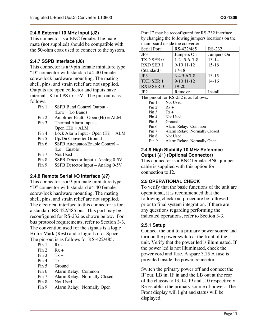
Port J7 may be reconfigured for RS-232 interface by changing the following jumpers locations on the main board inside the converter:

Serial Port

RS-422/485

RS-232

JP3

Jumpers On

Jumpers On

TXD SER 0

1-2 5-6 7-8

13-14

RXD SER 1

9-10 11-12

15-16

(Standard)

17-18


JP3

3-4 5-6 7-8

13-15

TXD SER 1

9-10 11-12

14-16

RXD SER 0

19-20


JP2

Remove

Install

The pinout for RS-232 is as follows:

Pin 1

Not Used

Pin 2

Rx +

Pin 3

Tx +

Pin 4

Not Used

Pin 5

Ground

Pin 6

Alarm Relay: Common

Pin 7

Alarm Relay: Normally Closed

Pin 8

Not Used

Pin 9

Alarm Relay: Normally Open

2.4.9High Stability 10 MHz Reference Output (J1) (Optional Connector)

This connector is a BNC female. BNC jumper cable is supplied with this option for connection to J2.

2.5 OPERATIONAL CHECK

To verify that the basic functions of the unit are operational, it is recommended that the following check-out procedure be followed prior to final system integration. If there are any questions regarding performing the indicated operations, refer to Section 3-3.

2.5.1 Setup

Connect the unit to a primary power source and turn on the power switch at the front of the unit. Verify that the power led is illuminated. If the power led is not illuminated, check the power cord and fuse. A spare 3.15 A fuse is provided inside the power connector.

Switch the primary power off and connect the IF out, LB in, IF in and the LB out at the rear of the chassis to J3, J4, J9 and J10 respectively. Re-establish the primary source of power. The Front display will light and status will be displayed.

Page 13

Page 13
Image 13
General Dynamics LT-3600, UP/DN CONVERTER L-BAND manual Operational Check

UP/DN CONVERTER L-BAND, LT-3600 specifications

The General Dynamics LT-3600 is an advanced UP/DN converter designed specifically for L-band applications, tailored to meet the rigorous demands of modern communication and broadcasting systems. Known for its reliability and versatility, the LT-3600 supports a wide range of operational environments, making it a preferred choice for military, aerospace, and commercial users.

One of the standout features of the LT-3600 is its ability to provide high-performance frequency translation with minimal signal degradation. The device operates within a frequency range typically from 950 MHz to 2150 MHz, allowing it to effectively handle various input and output frequencies, which is crucial for seamless integration into existing systems.

The LT-3600 employs advanced digital signal processing (DSP) technologies that enhance its performance in terms of linearity, noise figures, and phase stability. This results in superior signal clarity and reduced interference, ensuring that the converted signals maintain their integrity over long distances. The use of high-quality mixers and filters further contributes to its exceptional performance metrics, making it suitable for critical applications where signal fidelity is paramount.

In terms of usability, the LT-3600 boasts a user-friendly interface that facilitates ease of setup and operation. It is equipped with intuitive controls and indicators that provide real-time feedback on operational status, which is essential for monitoring performance during live operations. The device also offers options for both manual and remote control, enhancing its flexibility for different operational requirements.

Another significant characteristic of the LT-3600 is its robust design, featuring rugged components that can withstand adverse environments. The unit is engineered to comply with military standards, making it suitable for deployment in harsh conditions, including extreme temperatures and humidity. This reliability is critical for military and aerospace applications where equipment failures can lead to severe consequences.

Additionally, the LT-3600 supports various modulation schemes and can be easily integrated into systems requiring diverse communication protocols. This adaptability ensures that users can customize the unit to meet specific requirements, enhancing its appeal across multiple industries.

In summary, the General Dynamics LT-3600 UP/DN converter stands out for its advanced features, including superior signal quality, user-friendly operation, and rugged reliability. Its combination of innovative technologies and practical design makes it an essential component for anyone seeking high-performance L-band solutions in challenging environments.