English
ROTATING THE MITER TABLE
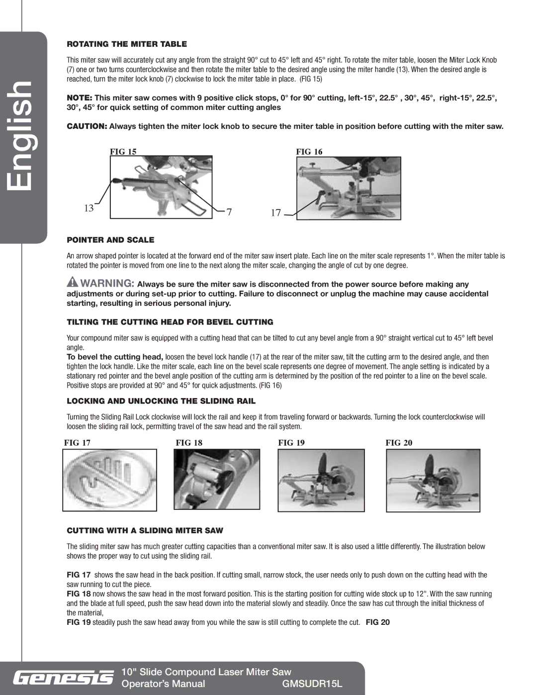
This miter saw will accurately cut any angle from the straight 90° cut to 45° left and 45° right. To rotate the miter table, loosen the Miter Lock Knob
(7)one or two turns counterclockwise and then rotate the miter table to the desired angle using the miter handle (13). When the desired angle is reached, turn the miter lock knob (7) clockwise to lock the miter table in place. (FIG 15)
NOTE: This miter saw comes with 9 positive click stops, 0° for 90° cutting,
CAUTION: Always tighten the miter lock knob to secure the miter table in position before cutting with the miter saw.
|
|
| FIG 15 |
|
|
| FIG 16 | |
13 |
|
|
|
|
| 7 | 17 |
|
|
|
|
|
| ||||
|
| |||||||
POINTER AND SCALE
An arrow shaped pointer is located at the forward end of the miter saw insert plate. Each line on the miter scale represents 1°. When the miter table is rotated the pointer is moved from one line to the next along the miter scale, changing the angle of cut by one degree.
![]() Warning: Always be sure the miter saw is disconnected from the power source before making any adjustments or during
Warning: Always be sure the miter saw is disconnected from the power source before making any adjustments or during
TILTING THE CUTTING HEAD FOR BEVEL CUTTING
Your compound miter saw is equipped with a cutting head that can be tilted to cut any bevel angle from a 90° straight vertical cut to 45° left bevel angle.
To bevel the cutting head, loosen the bevel lock handle (17) at the rear of the miter saw, tilt the cutting arm to the desired angle, and then tighten the lock handle. Like the miter scale, each line on the bevel scale represents one degree of movement. The angle setting is indicated by a stationary red pointer and the bevel angle position of the cutting arm is determined by the position of the red pointer to a line on the bevel scale. Positive stops are provided at 90° and 45° for quick adjustments. (FIG 16)
LOCKING AND UNLOCKING THE SLIDING RAIL
Turning the Sliding Rail Lock clockwise will lock the rail and keep it from traveling forward or backwards. Turning the lock counterclockwise will loosen the sliding rail lock, permitting travel of the saw head and the rail system.
FIG 17 |
| FIG 18 |
| FIG 19 | FIG 20 | |
|
|
|
|
|
|
|
|
|
|
|
|
|
|
CUTTING WITH A SLIDING MITER SAW
The sliding miter saw has much greater cutting capacities than a conventional miter saw. It is also used a little differently. The illustration below shows the proper way to cut using the sliding rail.
FIG 17 shows the saw head in the back position. If cutting small, narrow stock, the user needs only to push down on the cutting head with the saw running to cut the piece.
FIG 18 now shows the saw head in the most forward position. This is the starting position for cutting wide stock up to 12". With the saw running and the blade at full speed, push the saw head down into the material slowly and steadily. Once the saw has cut through the initial thickness of the material,
FIG 19 steadily push the saw head away from you while the saw is still cutting to complete the cut. FIG 20
10" Slide Compound Laser Miter Saw
Operator’s Manual | GMSUDR15L |
