English
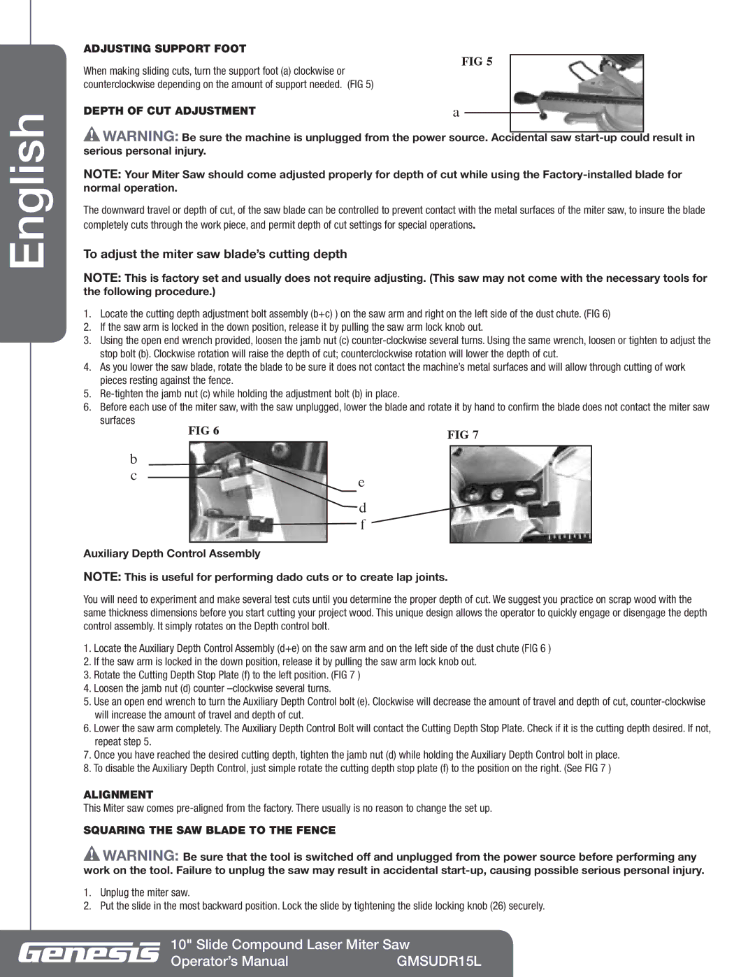
ADJUSTING SUPPORT FOOT | FIG 5 | ||
When making sliding cuts, turn the support foot (a) clockwise or | |||
|
| ||
counterclockwise depending on the amount of support needed. (FIG 5) |
|
| |
DEPTH OF CUT ADJUSTMENT | a |
| |
| |||
![]() Warning: Be sure the machine is unplugged from the power source. Accidental saw
Warning: Be sure the machine is unplugged from the power source. Accidental saw
NOTE: Your Miter Saw should come adjusted properly for depth of cut while using the
The downward travel or depth of cut, of the saw blade can be controlled to prevent contact with the metal surfaces of the miter saw, to insure the blade completely cuts through the work piece, and permit depth of cut settings for special operations.
To adjust the miter saw blade’s cutting depth
NOTE: This is factory set and usually does not require adjusting. (This saw may not come with the necessary tools for the following procedure.)
1.Locate the cutting depth adjustment bolt assembly (b+c) ) on the saw arm and right on the left side of the dust chute. (FIG 6)
2.If the saw arm is locked in the down position, release it by pulling the saw arm lock knob out.
3.Using the open end wrench provided, loosen the jamb nut (c)
4.As you lower the saw blade, rotate the blade to be sure it does not contact the machine’s metal surfaces and will allow through cutting of work pieces resting against the fence.
5.
6.Before each use of the miter saw, with the saw unplugged, lower the blade and rotate it by hand to confirm the blade does not contact the miter saw
surfaces | FIG 6 |
|
| FIG 7 | |||
|
|
| |||||
b |
|
|
|
|
|
|
|
|
|
|
|
|
|
| |
c |
|
|
|
|
| e |
|
|
|
|
|
|
| ||
|
|
|
|
|
|
| |
|
|
|
|
|
| d |
|
|
|
|
|
|
| f |
|
|
|
|
|
|
|
|
|
Auxiliary Depth Control Assembly
NOTE: This is useful for performing dado cuts or to create lap joints.
You will need to experiment and make several test cuts until you determine the proper depth of cut. We suggest you practice on scrap wood with the same thickness dimensions before you start cutting your project wood. This unique design allows the operator to quickly engage or disengage the depth control assembly. It simply rotates on the Depth control bolt.
1.Locate the Auxiliary Depth Control Assembly (d+e) on the saw arm and on the left side of the dust chute (FIG 6 )
2.If the saw arm is locked in the down position, release it by pulling the saw arm lock knob out.
3.Rotate the Cutting Depth Stop Plate (f) to the left position. (FIG 7 )
4.Loosen the jamb nut (d) counter
5.Use an open end wrench to turn the Auxiliary Depth Control bolt (e). Clockwise will decrease the amount of travel and depth of cut,
6.Lower the saw arm completely. The Auxiliary Depth Control Bolt will contact the Cutting Depth Stop Plate. Check if it is the cutting depth desired. If not, repeat step 5.
7.Once you have reached the desired cutting depth, tighten the jamb nut (d) while holding the Auxiliary Depth Control bolt in place.
8.To disable the Auxiliary Depth Control, just simple rotate the cutting depth stop plate (f) to the position on the right. (See FIG 7 )
ALIGNMENT
This Miter saw comes
SQUARING THE SAW BLADE TO THE FENCE
![]() Warning: Be sure that the tool is switched off and unplugged from the power source before performing any work on the tool. Failure to unplug the saw may result in accidental
Warning: Be sure that the tool is switched off and unplugged from the power source before performing any work on the tool. Failure to unplug the saw may result in accidental
1.Unplug the miter saw.
2.Put the slide in the most backward position. Lock the slide by tightening the slide locking knob (26) securely.
10" Slide Compound Laser Miter Saw
Operator’s Manual | GMSUDR15L |