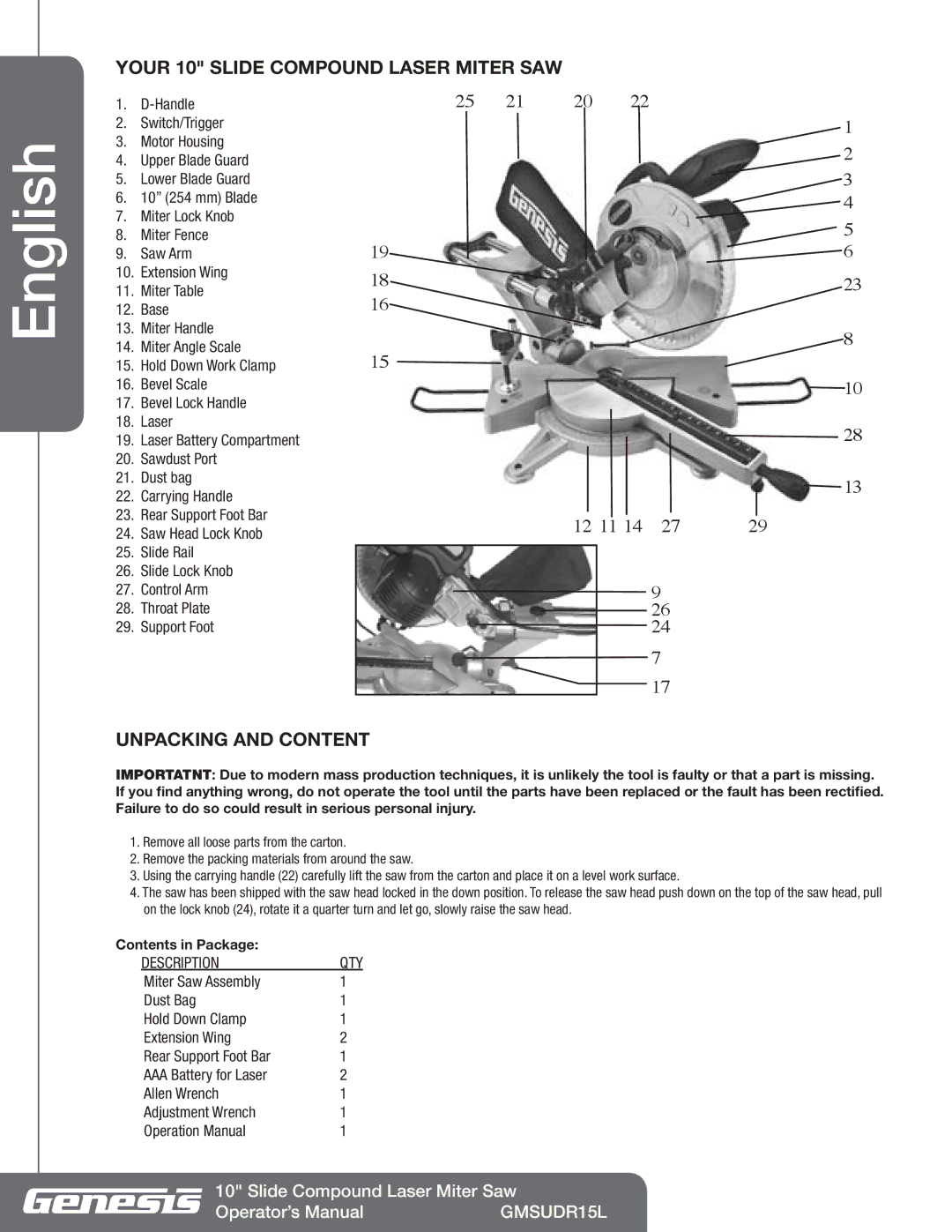
YOUR 10" SLIDE COMPOUND LASER MITER SAW
English
1.
2.Switch/Trigger
3.Motor Housing
4.Upper Blade Guard
5.Lower Blade Guard
6.10” (254 mm) Blade
7.Miter Lock Knob
8.Miter Fence
9.Saw Arm
10.Extension Wing
11.Miter Table
12.Base
13.Miter Handle
14.Miter Angle Scale
15.Hold Down Work Clamp
16.Bevel Scale
17.Bevel Lock Handle
18.Laser
19.Laser Battery Compartment
20.Sawdust Port
21.Dust bag
22.Carrying Handle
23.Rear Support Foot Bar
24.Saw Head Lock Knob
25.Slide Rail
26.Slide Lock Knob
27.Control Arm
28.Throat Plate
29.Support Foot
19
18
16
15
25 21 20 22
1
2
3
4
5 ![]() 6
6
23
8
10
28
13
12 11 14 | 27 | 29 |
9
26
24
7
17
UNPACKING AND CONTENT
IMPORTATNT: Due to modern mass production techniques, it is unlikely the tool is faulty or that a part is missing. If you find anything wrong, do not operate the tool until the parts have been replaced or the fault has been rectified. Failure to do so could result in serious personal injury.
1.Remove all loose parts from the carton.
2.Remove the packing materials from around the saw.
3.Using the carrying handle (22) carefully lift the saw from the carton and place it on a level work surface.
4.The saw has been shipped with the saw head locked in the down position. To release the saw head push down on the top of the saw head, pull on the lock knob (24), rotate it a quarter turn and let go, slowly raise the saw head.
Contents in Package: |
| |
| DESCRIPTION | QTY |
| Miter Saw Assembly | 1 |
| Dust Bag | 1 |
| Hold Down Clamp | 1 |
| Extension Wing | 2 |
| Rear Support Foot Bar | 1 |
| AAA Battery for Laser | 2 |
| Allen Wrench | 1 |
| Adjustment Wrench | 1 |
| Operation Manual | 1 |
10" Slide Compound Laser Miter Saw
Operator’s Manual | GMSUDR15L |