English
ASSEMBLY AND ADJUSTMENTS
![]() Warning: DO NOT connect your compound miter saw to the power source until the machine is completely assembled, all necessary adjustments made, and you have read and understand the entire operator’s manual.
Warning: DO NOT connect your compound miter saw to the power source until the machine is completely assembled, all necessary adjustments made, and you have read and understand the entire operator’s manual.
Your saw comes from the factory fully adjusted and requires only minor assembly to prepare the miter saw for operation. The Dust Bag, Support Extension Wings, Rear Support Foot Bar and 2- AAA Batteries in the Laser Battery Compartment should be installed before using the saw.
DUST BAG
A dust bag is provided for use with your miter saw. It is installed over the sawdust port located at the rear of the upper blade guard. Squeeze the two metal clips to open the mouth of the bag and slide onto the sawdust port. Release pressure on the clips and the metal ring at the bag’s opening should lock in the grooves of the sawdust port.
The dust bag should be checked often and if more than half full, remove the bag by simply reversing the installation procedure. Dispose of the accumulated saw dust in the dust bag and then reinstall the dust bag before resuming operation of the miter saw.
SUPPORT EXTENSION WINGS
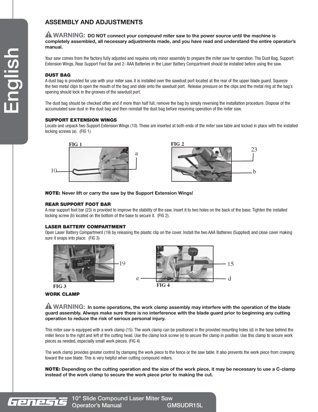
Locate and unpack two Support Extension Wings (10). These are inserted at both ends of the miter saw table and locked in place with the installed locking screws (a). (FIG 1)
| FIG 1 | a | FIG 2 | 23 | |
|
|
|
| ||
|
|
|
|
| |
10 |
|
|
|
| b |
|
|
|
|
|
|
NOTE: Never lift or carry the saw by the Support Extension Wings!
REAR SUPPORT FOOT BAR
A rear support foot bar (23) is provided to improve the stability of the saw. Insert it to two holes on the back of the base. Tighten the installed locking screw (b) located on the bottom of the base to secure it. (FIG 2).
LASER BATTERY COMPARTMENT
Open Laser Battery Compartment (19) by releasing the plastic clip on the cover. Install the two AAA Batteries (Supplied) and close cover making sure it snaps into place. (FIG 3)
|
|
|
| 19 |
| 15 |
|
|
|
|
| ||
|
|
|
| |||
|
|
|
| e |
| d |
| FIG 3 |
|
| FIG 4 |
| |
WORK CLAMP
![]() Warning: In some operations, the work clamp assembly may interfere with the operation of the blade guard assembly. Always make sure there is no interference with the blade guard prior to beginning any cutting operation to reduce the risk of serious personal injury.
Warning: In some operations, the work clamp assembly may interfere with the operation of the blade guard assembly. Always make sure there is no interference with the blade guard prior to beginning any cutting operation to reduce the risk of serious personal injury.
This miter saw is equipped with a work clamp (15). The work clamp can be positioned in the provided mounting holes (d) in the base behind the miter fence to the right and left of the cutting head. Use the clamp lock screw (e) to secure the clamp in position. Use this clamp to secure work pieces as needed, especially small work pieces. (FIG 4)
The work clamp provides greater control by clamping the work piece to the fence or the saw table. It also prevents the work piece from creeping toward the saw blade. This is very helpful when cutting compound miters.
NOTE: Depending on the cutting operation and the size of the work piece, it may be necessary to use a
10" Slide Compound Laser Miter Saw
Operator’s Manual | GMSUDR15L |