11 | DISASSEMBLY PROCEDURE | ||
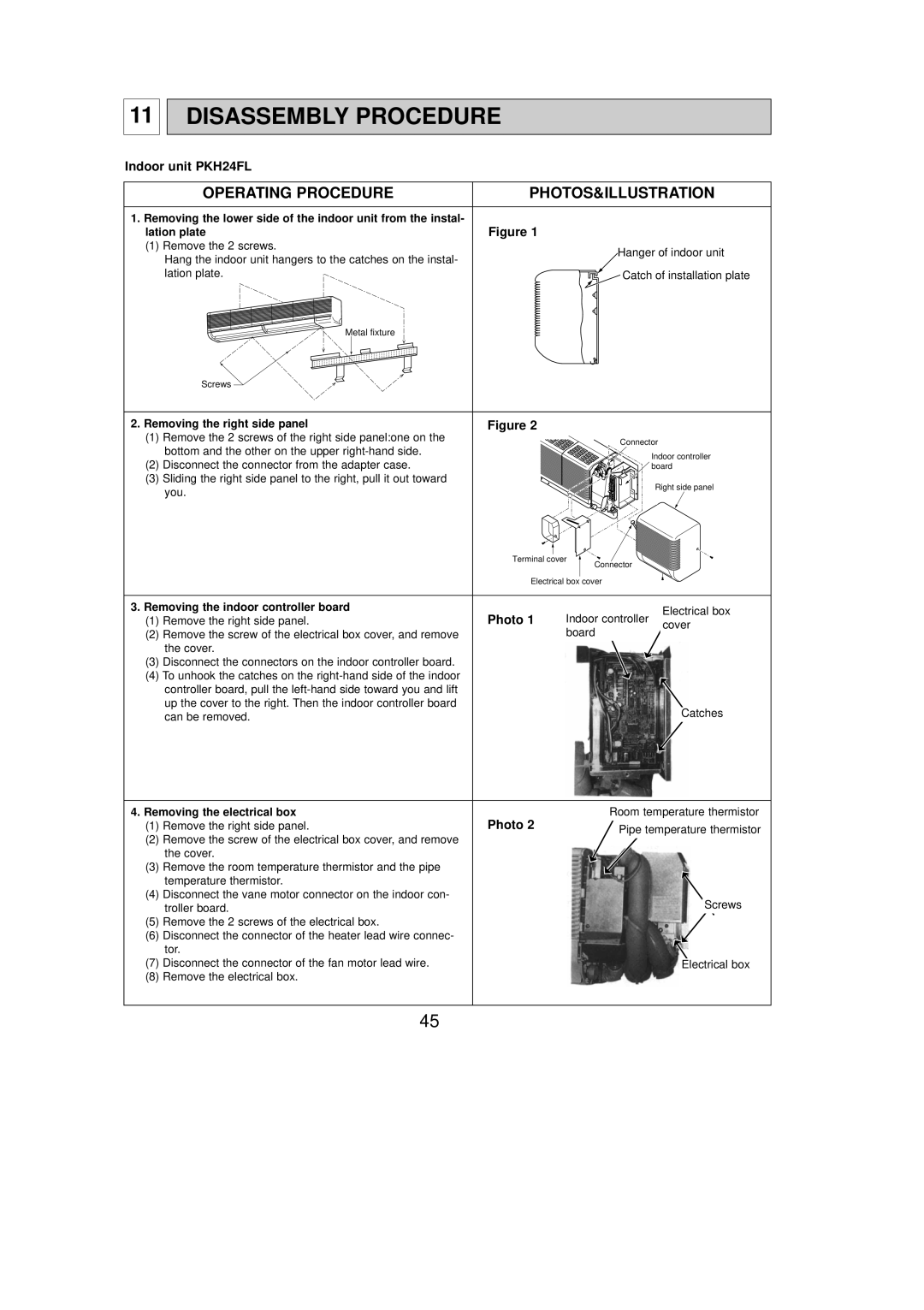
Indoor unit PKH24FL |
| ||
| OPERATING PROCEDURE | PHOTOS&ILLUSTRATION | |
1. Removing the lower side of the indoor unit from the instal- | Figure 1 | ||
lation plate | |||
(1) Remove the 2 screws. | Hanger of indoor unit | ||
| Hang the indoor unit hangers to the catches on the instal- | ||
|
| ||
| lation plate. | Catch of installation plate | |
| Metal fixture |
| |
| Screws |
| |
2. Removing the right side panel | Figure 2 | ||
(1) Remove the 2 screws of the right side panel:one on the | Connector | ||
| bottom and the other on the upper | ||
| Indoor controller | ||
(2) Disconnect the connector from the adapter case. | |||
board | |||
(3) Sliding the right side panel to the right, pull it out toward | Right side panel | ||
| you. | ||
|
| ||
| Terminal cover |
| Connector |
|
|
|
| ||
|
|
|
|
|
| ||||
|
|
|
|
|
|
|
| ||
| Electrical box |
| cover |
|
|
|
| ||
|
|
|
|
|
| ||||
|
|
|
|
|
|
|
|
|
|
3. Removing the indoor controller board |
|
|
|
|
|
|
|
|
|
Photo 1 |
|
|
|
| Electrical box |
|
| ||
(1) Remove the right side panel. | Indoor controller |
|
|
| |||||
| cover |
|
| ||||||
(2) Remove the screw of the electrical box cover, and remove |
| board |
|
| |||||
|
|
|
|
|
| ||||
|
|
|
|
| |||||
the cover. |
|
|
|
|
|
|
|
|
|
(3) Disconnect the connectors on the indoor controller board. |
|
|
|
|
|
|
|
|
|
(4) To unhook the catches on the |
|
|
|
|
|
|
|
|
|
controller board, pull the |
|
|
|
|
|
|
|
|
|
up the cover to the right. Then the indoor controller board |
|
|
|
|
|
|
|
|
|
can be removed. |
|
|
|
|
|
| Catches |
| |
|
|
|
|
|
|
|
|
| |
4. Removing the electrical box | Photo 2 | Room temperature thermistor |
(1) Remove the right side panel. | Pipe temperature thermistor | |
|
|
(2)Remove the screw of the electrical box cover, and remove the cover.
(3) | Remove the room temperature thermistor and the pipe |
|
|
|
| temperature thermistor. |
|
|
|
(4) | Disconnect the vane motor connector on the indoor con- |
|
|
|
| troller board. |
| Screws |
|
|
|
|
| |
(5) | Remove the 2 screws of the electrical box. |
|
|
|
(6) | Disconnect the connector of the heater lead wire connec- |
|
|
|
| tor. |
|
|
|
(7) | Disconnect the connector of the fan motor lead wire. |
|
| |
Electrical box |
| |||
(8) | Remove the electrical box. |
|
|
|
|
|
|
|
|
45
