8
OPERATION FLOW-CHART
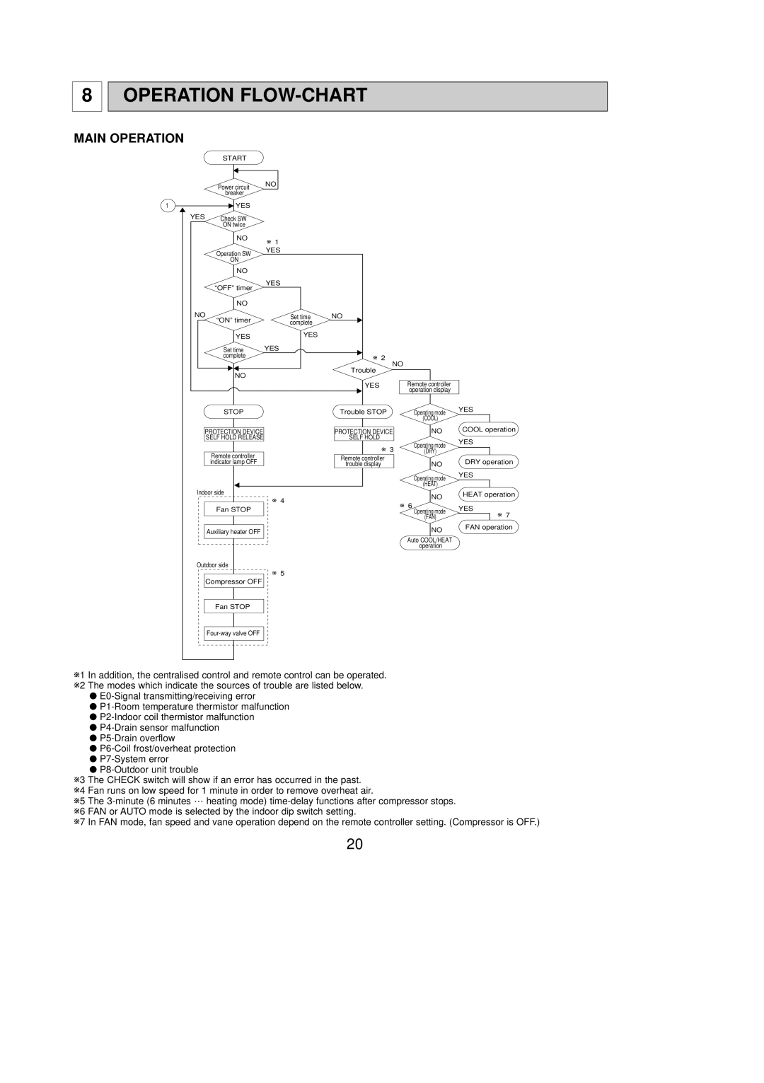
MAIN OPERATION
| START |
|
|
| Power circuit | NO |
|
|
|
| |
| breaker |
|
|
1 | YES |
|
|
YES | Check SW |
|
|
| ON twice |
|
|
| NO | w 1 |
|
|
|
| |
| Operation SW | YES |
|
|
|
| |
| ON |
|
|
| NO |
|
|
| “OFF” timer | YES |
|
|
|
| |
| NO |
|
|
NO | “ON” timer | Set time | NO |
| complete |
| |
|
|
| |
| YES | YES |
|
| Set time | YES |
|
| complete |
| w 2 |
|
|
|
NO
Trouble
NO
YES | Remote controller |
| operation display |
STOP | Trouble STOP | Operating mode | YES | |
|
| (COOL) |
| |
PROTECTION DEVICE | PROTECTION DEVICE | NO | COOL operation | |
SELF HOLD RELEASE | SELF HOLD |
| YES | |
| w 3 | Operating mode | ||
|
| |||
Remote controller | (DRY) |
| ||
Remote controller |
|
| ||
indicator lamp OFF |
| DRY operation | ||
trouble display | NO | |||
|
| |||
|
| Operating mode | YES | |
|
|
| ||
|
| (HEAT) |
| |
Indoor side | w 4 | NO | HEAT operation | |
|
| |||
| w 6 |
| ||
Fan STOP |
| YES | ||
| Operating mode | |||
|
| (FAN) | w 7 | |
Auxiliary heater OFF |
| NO | FAN operation | |
|
| |||
|
| Auto COOL/HEAT |
| |
|
| operation |
|
Outdoor side
w5
Compressor OFF
Fan STOP
w1 In addition, the centralised control and remote control can be operated. w2 The modes which indicate the sources of trouble are listed below.
●
●
●
●
●
●
●
●
w3 The CHECK switch will show if an error has occurred in the past. w4 Fan runs on low speed for 1 minute in order to remove overheat air.
w5 The
w7 In FAN mode, fan speed and vane operation depend on the remote controller setting. (Compressor is OFF.)
20