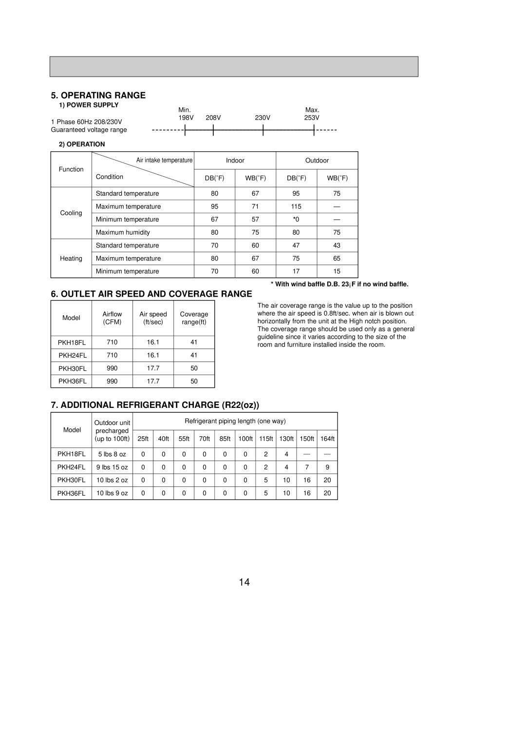
5.OPERATING RANGE
1)POWER SUPPLY
| Min. |
|
| Max. |
1 Phase 60Hz 208/230V | 198V | 208V | 230V | 253V |
|
|
|
|
Guaranteed voltage range
2) OPERATION
| Air intake temperature | Indoor |
| Outdoor | ||
Function |
|
|
|
|
| |
| Condition | DB(˚F) | WB(˚F) | DB(˚F) | WB(˚F) | |
| Standard temperature | 80 | 67 | 95 | 75 | |
Cooling | Maximum temperature | 95 | 71 | 115 | — | |
Minimum temperature | 67 | 57 | *0 | — | ||
| ||||||
| Maximum humidity | 80 | 75 | 80 | 75 | |
| Standard temperature | 70 | 60 | 47 | 43 | |
Heating | Maximum temperature | 80 | 67 | 75 | 65 | |
| Minimum temperature | 70 | 60 | 17 | 15 | |
* With wind baffle D.B. 23°F if no wind baffle.
6. OUTLET AIR SPEED AND COVERAGE RANGE
Model | Airflow | Air speed | Coverage | |
(CFM) | (ft/sec) | range(ft) | ||
| ||||
|
|
|
| |
PKH18FL | 710 | 16.1 | 41 | |
|
|
|
| |
PKH24FL | 710 | 16.1 | 41 | |
|
|
|
| |
PKH30FL | 990 | 17.7 | 50 | |
|
|
|
| |
PKH36FL | 990 | 17.7 | 50 | |
|
|
|
|
The air coverage range is the value up to the position where the air speed is 0.8ft/sec. when air is blown out horizontally from the unit at the High notch position.
The coverage range should be used only as a general guideline since it varies according to the size of the room and furniture installed inside the room.
7. ADDITIONAL REFRIGERANT CHARGE (R22(oz))
Model | Outdoor unit |
|
| Refrigerant piping length (one way) |
|
|
|
|
|
| |||||
precharged |
|
|
|
|
|
|
|
|
|
|
|
|
|
| |
|
|
|
|
|
|
|
|
|
|
|
|
|
| ||
| (up to 100ft) | 25ft | 40ft | 55ft | 70ft | 85ft | 100ft | 115ft | 130ft | 150ft | 164ft | ||||
|
|
|
|
|
|
|
|
|
|
|
|
|
|
|
|
PKH18FL | 5 lbs 8 oz | 0 | 0 | 0 | 0 | 0 | 0 | 2 | 4 |
|
|
|
|
|
|
|
|
|
|
|
| ||||||||||
|
|
|
|
|
|
|
|
|
|
|
|
|
|
|
|
PKH24FL | 9 lbs 15 oz | 0 | 0 | 0 | 0 | 0 | 0 | 2 | 4 | 7 |
| 9 |
| ||
|
|
|
|
|
|
|
|
|
|
|
|
|
|
|
|
PKH30FL | 10 lbs 2 oz | 0 | 0 | 0 | 0 | 0 | 0 | 5 | 10 | 16 | 20 | ||||
|
|
|
|
|
|
|
|
|
|
|
|
|
|
|
|
PKH36FL | 10 lbs 9 oz | 0 | 0 | 0 | 0 | 0 | 0 | 5 | 10 | 16 | 20 | ||||
|
|
|
|
|
|
|
|
|
|
|
|
|
|
|
|
14