Contents
Contents
Revised EDITION-A
Features
Part Names and Functions
Specifications
Models PKH18FL, PKH24FL, PKH30FL, PKH36FL
Data
Models PKH18FL, PKH24FL, PKH30FL, PKH36FL Performance Data
Heating Capacity
PKH18FL
Performance Curve
PKH24FL
PKH36FL
Heating Mode
PKH18FL Cooling Mode
Condensing Pressure and Suction Pressure
PKH24FL Cooling Mode
Indoor DB temperature F 80 psi.G Pressure Suction
PKH30FL Cooling Mode
PKH36FL Cooling Mode
Standard Operation Data
SHF PKH18FL PKH24FL PKH30FL PKH36FL
Outlet AIR Speed and Coverage Range
Operating Range
With wind baffle D.B F if no wind baffle
Noise Criterion Curves
PKH30FL
PKH36FL
Band Center FREQUENCIES, Hz
PKH24FL
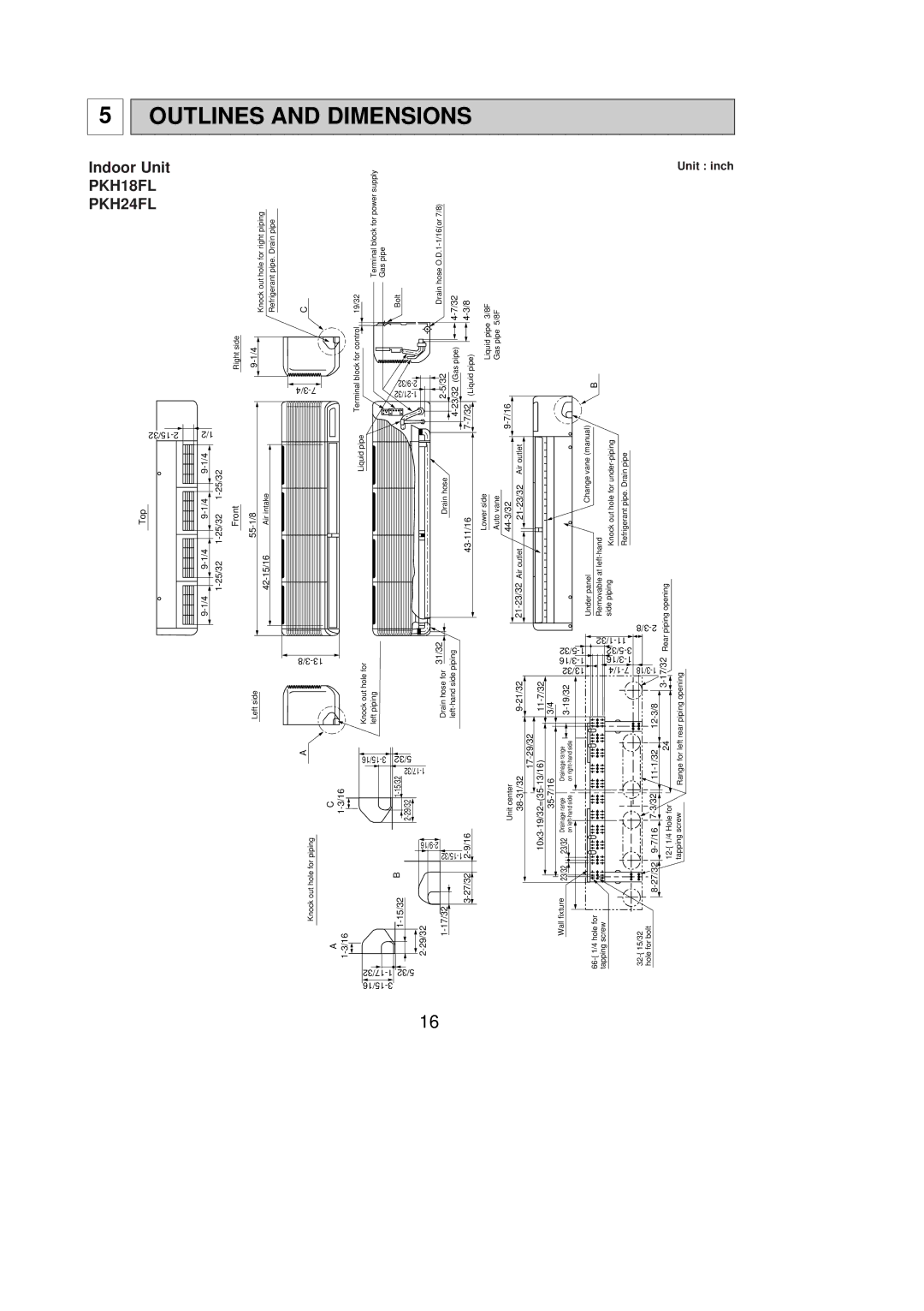
Outlines
Unit inch
PKH36FL PKH30FL
Inch
Wireless Remote Controller
Refrigerant System Diagram
PKH18FL PKH24FL PKH30FL PKH36FL
Wiring Diagram
Models PKH18FL, PKH24FL, PKH30FL, PKH36FL Wiring Diagram
Operation FLOW-CHART
Main Operation
Cooling Operation
DRY Operation
YES
Heating Operation
YES FAN Speed no
Microprocessor Control
Outline of Microprocessor Control
Cool operation time chart
How to operate
Indoor Unit Control
Cool operation
Compressor control
Start condition
Coil frost protection
Termination conditions
Auto vane control
Auto Return
Detecting abnormalities in the outdoor unit
DRY operation time chart How to operate
DRY operation
Fan control in DRY operation
Heat operation
Heat operation time chart How to operate
Display in Heat operation
Booster heater control
Overheat protection
Overheat prevention
Indoor coil temperature abnormality detection
Defrosting operation
Mode change
Initial mode
Temperature range
COOL/DRY operation
Auto vane control
Auto return
Timer function
Timer operation
Test run
Emergency operation
Before emergency operation
Dip switch and jumper connector functions
On remote controller board On indoor controller board
Indoor FAN Control
Wireless remote controller pair number setting operation
Model No
Troubleshooting
Self-check
Other Troubles and Causes
Wrong Wiring on Site
Between remote controller and indoor unit
HOW to Check the Parts
Check points
Disassembly Procedure
Operating Procedure PHOTOS&ILLUSTRATION
Indoor unit PKH24FL
Photo
Removing the intake grilles
Removing the vane motor
Removing the drain pan
Removing the line flow fan and the fan motor
Operating Procedure Photos
Removing the electrical heater
Parts List
Electrical Parts PKH18FL PKH24FL PKH30FL PKH36FL
Qty / set Wiring Parts No Parts Name Specifications
T7W E13
T7W E14
R01 12G 621
Structural Parts
PKH24FL PKH30FL PKH36FL
Page
Distributed in Dec No.OC276 New publication, effective Nov
Specifications are subject to change without notice