2
PART NAMES AND FUNCTIONS
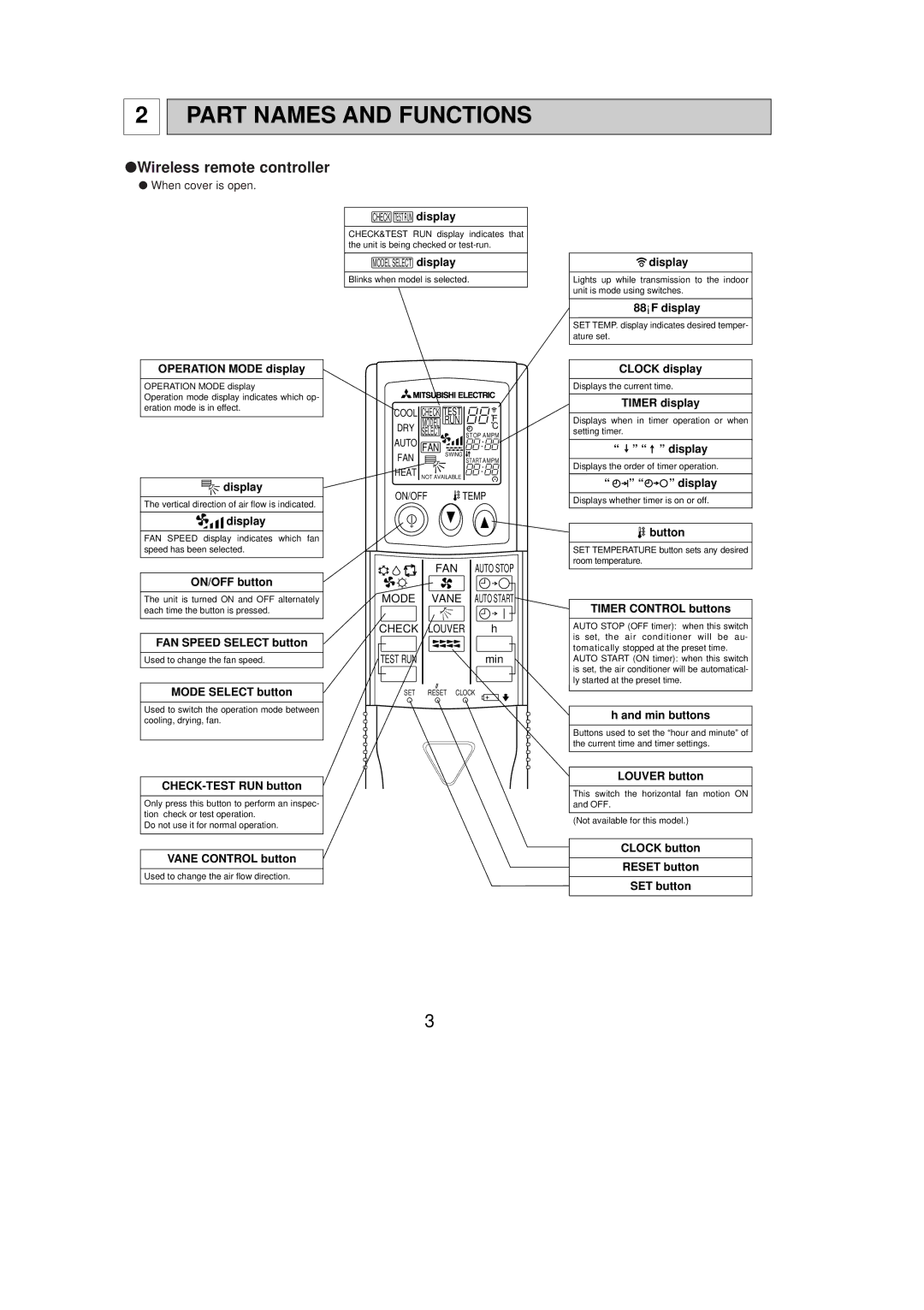
●Wireless remote controller
●When cover is open.
OPERATION MODE display
OPERATION MODE display
Operation mode display indicates which op- eration mode is in effect.
![]()
![]() display
display
The vertical direction of air flow is indicated.
![]()
![]() display
display
FAN SPEED display indicates which fan speed has been selected.
ON/OFF button
The unit is turned ON and OFF alternately each time the button is pressed.
FAN SPEED SELECT button
Used to change the fan speed.
MODE SELECT button
Used to switch the operation mode between cooling, drying, fan.
CHECK-TEST RUN button
Only press this button to perform an inspec- tion check or test operation.
Do not use it for normal operation.
VANE CONTROL button
Used to change the air flow direction.
CHECK TESTRUN display
CHECK&TEST RUN display indicates that the unit is being checked or
MODEL SELECT display
Blinks when model is selected.
COOL CHECK | TEST | ˚F | |
MODEL | RUN | ||
˚C | |||
DRY SELECT |
| STOP AMPM | |
AUTO FAN | SWING |
| |
FAN | START AMPM | ||
| |||
HEAT NOT AVAILABLE |
| ||
ON/OFF ![]() TEMP
TEMP
| FAN | AUTO STOP |
MODE | VANE | AUTO START |
CHECK | LOUVER | h |
TEST RUN |
| min |
SET | RESET CLOCK | |
![]() display
display
Lights up while transmission to the indoor unit is mode using switches.
88°F display
SET TEMP. display indicates desired temper- ature set.
CLOCK display
Displays the current time.
TIMER display
Displays when in timer operation or when setting timer.
“ ![]() ” “
” “ ![]() ” display
” display
Displays the order of timer operation.
“ ![]()
![]() ” “
” “![]()
![]() ” display
” display
Displays whether timer is on or off.
![]() button
button
SET TEMPERATURE button sets any desired room temperature.
TIMER CONTROL buttons
AUTO STOP (OFF timer): when this switch is set, the air conditioner will be au- tomatically stopped at the preset time.
AUTO START (ON timer): when this switch is set, the air conditioner will be automatical- ly started at the preset time.
h and min buttons
Buttons used to set the “hour and minute” of the current time and timer settings.
LOUVER button
This switch the horizontal fan motion ON and OFF.
(Not available for this model.)
CLOCK button
RESET button
SET button
3