E. Vent Diagrams |
|
|
|
|
|
|
|
Top Vent - Horizontal Termination |
|
|
| WARNING | |||
|
|
|
|
|
| ||
Note: The 6000/8000 series fireplaces can adapt to SLP series |
| Fire Risk. | Explosion Risk. | ||||
vent pipe, if desired. |
|
|
| Do NOT pack insulation or other combustibles | |||
When venting off the top of the unit, use a | adapter and a |
| between ceiling firestops. | ||||
minimum 48 inch vertical section of SLP series vent pipe. |
| • ALWAYS maintain specified clearances around | |||||
A |
| venting and firestop systems. | |||||
section of SLP series vent pipe. |
|
|
| • Install wall shield and ceiling firestops as speci- | |||
After the 48 inch vertical section, the venting table rules must be |
| fied. |
|
| |||
followed. The first 48 inch vertical section is NOT counted as part |
| Failure to keep insulation or other material away | |||||
of the vertical components in the table. It is still counted as part of |
| from vent pipe may cause fire. | |||||
the overall maximum run. All venting table rules for the vent run |
|
|
|
| |||
must still be followed. |
|
|
|
|
| WARNING | |
|
|
|
|
|
| ||
Example: DVP pipe 3 ft. min. vertical = 11 ft. max. horizontal |
| Fire Risk. |
|
| |||
SLP pipe 7 ft. min. vertical = 11 ft. max. horizontal |
| • When using | |||||
|
|
|
|
| SS termination caps on top vented fireplaces, a | ||
|
|
|
|
| 6 inch minimum vertical vent section is required | ||
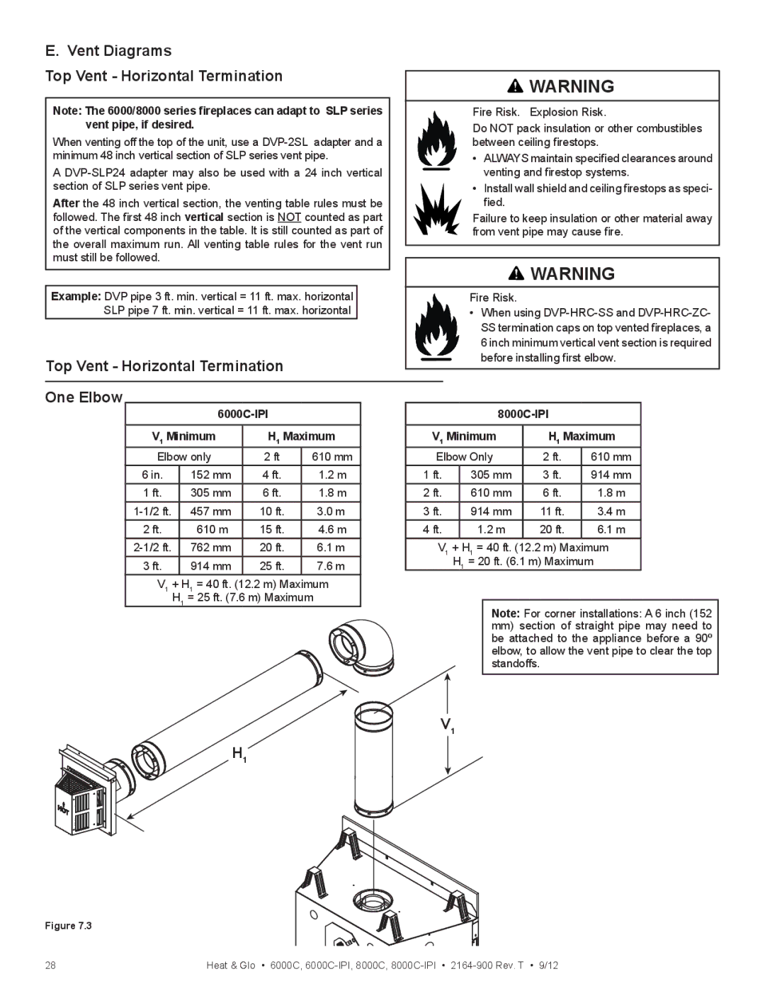
Top Vent - Horizontal Termination |
|
| before installing first elbow. | ||||
|
|
|
|
| |||
One Elbow |
|
|
|
|
| ||
|
|
|
| ||||
V1 Minimum | H1 Maximum | V1 Minimum | H1 Maximum | ||||
Elbow only | 2 ft | 610 mm | Elbow Only | 2 ft. | 610 mm | ||
6 in. | 152 mm | 4 ft. | 1.2 m | 1 ft. | 305 mm | 3 ft. | 914 mm |
1 ft. | 305 mm | 6 ft. | 1.8 m | 2 ft. | 610 mm | 6 ft. | 1.8 m |
457 mm | 10 ft. | 3.0 m | 3 ft. | 914 mm | 11 ft. | 3.4 m | |
2 ft. | 610 m | 15 ft. | 4.6 m | 4 ft. | 1.2 m | 20 ft. | 6.1 m |
762 mm | 20 ft. | 6.1 m | V1 | + H1 = 40 ft. (12.2 m) Maximum | |||
3 ft. | 914 mm | 25 ft. | 7.6 m |
| H1 = 20 ft. (6.1 m) Maximum | ||
V1 | + H1 = 40 ft. (12.2 m) Maximum |
|
|
|
| ||
| H1 = 25 ft. (7.6 m) Maximum |
| Note: For corner installations: A 6 inch (152 | ||||
|
|
|
|
| |||
|
|
|
|
| mm) section of straight pipe may need to | ||
|
|
|
|
| be attached to the appliance before a 90º | ||
|
|
|
|
| elbow, to allow the vent pipe to clear the top | ||
|
|
|
|
| standoffs. |
| |
H1
V1
Figure 7.3
28 | Heat & Glo • 6000C, |