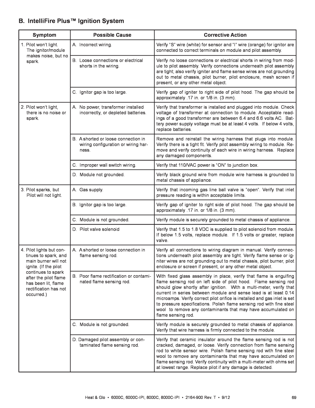
B. IntelliFire Plus™ Ignition System
Symptom | Possible Cause | Corrective Action | |
|
|
| |
1. Pilot won’t light. | A. Incorrect wiring. | Verify “S” wire (white) for sensor and “I” wire (orange) for ignitor are | |
The ignitor/module |
| connected to correct terminals on module and pilot assembly. | |
makes noise, but no |
|
| |
B. Loose connections or electrical | Verify no loose connections or electrical shorts in wiring from mod- | ||
spark. | |||
| shorts in the wiring. | ule to pilot assembly. Verify connections underneath pilot assembly | |
|
| are tight; also verify igniter and flame sense wires are not grounding | |
|
| out to metal chassis, pilot burner, pilot enclosure, mesh screen if | |
|
| present, or any other metal object. | |
|
|
| |
| C. Ignitor gap is too large. | Verify gap of igniter to right side of pilot hood. The gap should be | |
|
| approximately .17 in. or 1/8 in. (3 mm). | |
|
|
| |
2. Pilot won’t light, | A. No power, transformer installed | Verify that transformer is installed and plugged into module. Check | |
there is no noise or | incorrectly, or depleted batteries. | voltage of transformer at connection to module. Acceptable read- | |
spark. |
| ings of a good transformer are between 6.4 and 6.6 volts AC. Bat- | |
|
| tery power supply voltage must be at least 4 volts. If below 4 volts, | |
|
| replace batteries. | |
|
|
| |
| B. A shorted or loose connection in | Remove and reinstall the wiring harness that plugs into module. | |
| wiring configuration or wiring har- | Verify there is a tight fit. Verify pilot assembly wiring to module. Re- | |
| ness. | move and verify continuity of each wire in wiring harness. Replace | |
|
| any damaged components. | |
|
|
| |
| C. Improper wall switch wiring. | Verify that 110/VAC power is “ON” to junction box. | |
|
|
| |
| D. Module not grounded. | Verify black ground wire from module wire harness is grounded to | |
|
| metal chassis of appliance. | |
|
|
| |
3. Pilot sparks, but | A. Gas supply. | Verify that incoming gas line ball valve is “open”. Verify that inlet | |
Pilot will not light. |
| pressure reading is within acceptable limits. | |
|
|
| |
| B. Ignitor gap is too large. | Verify gap of igniter to right side of pilot hood. The gap should be | |
|
| approximately .17 in. or 1/8 in. (3 mm). | |
|
|
| |
| C. Module is not grounded. | Verify module is securely grounded to metal chassis of appliance. | |
|
|
| |
| D. Pilot valve solenoid | Verify that 1.5 to 1.8 VDC is supplied to pilot solenoid from module. | |
|
| If below 1.5 volts, replace module. If 1.5 volts or greater, replace | |
|
| valve. | |
|
|
| |
4. Pilot lights but con- | A. A shorted or loose connection in | Verify all connections to wiring diagram in manual. Verify connec- | |
tinues to spark, and | flame sensing rod. | tions underneath pilot assembly are tight. Verify flame sense or ig- | |
main burner will not |
| niter wires are not grounding out to metal chassis, pilot burner, pilot | |
ignite. (If the pilot |
| enclosure or screen if present, or any other metal object. | |
continues to spark |
|
| |
B. Poor flame rectification or contami- | With fixed glass assembly in place, verify that flame is engulfing | ||
after the pilot flame | |||
nated flame sensing rod. | flame sensing rod on left side of pilot hood. Flame sensing rod | ||
has been lit, flame | |||
| should glow shortly after ignition. With a | ||
rectification has not |
| ||
| current in series between module and sense lead is at least 0.14 | ||
occurred.) |
| ||
| microamps. Verify correct pilot orifice is installed and gas inlet is set | ||
|
| ||
|
| to pressure specifications. Polish flame sensing rod with fine steel | |
|
| wool to remove any contaminants that may have accumulated on | |
|
| flame sensing rod. | |
|
|
| |
| C. Module is not grounded. | Verify module is securely grounded to metal chassis of appliance. | |
|
| Verify that wire harness is firmly connected to the module. | |
|
|
| |
| D. Damaged pilot assembly or con- | Verify that ceramic insulator around the flame sensing rod is not | |
| taminated flame sensing rod. | cracked, damaged, or loose. Verify connection from flame sensing | |
|
| rod to white sensor wire. Polish flame sensing rod with fine steel | |
|
| wool to remove any contaminants that may have accumulated on | |
|
| flame sensing rod. Verify continuity with a | |
|
| at lowest range. Replace pilot if any damage is detected. | |
|
|
|
Heat & Glo • 6000C, | 69 |