H. IPI Battery Tray/Battery Installation
The IntelliFire PlusTM system has a battery backup option. Battery longevity and performance will be affected by the service temperatures of this appliance.
NOTICE: Batteries should only be used as a power source in the event of an emergency such as an outage.
I. Control Module Operation
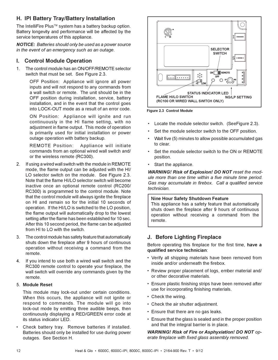
1.The control module has an ON/OFF/REMOTE selector switch that must be set. See Figure 2.3.
OFF Position: Appliance will ignore all power inputs and will not respond to any commands from a wall switch or remote. The unit should be in the OFF position during installation, service, battery installation, and in the event that the control goes into
ON Position: Appliance will ignite and run continuously in the HI flame setting, with no adjustment in flame output. This mode of operation is primarily used for initial installation or power outage operation with battery backup.
REMOTE Position: Appliance will initiate commands from an optional wired wall switch and/ or the wireless remote (RC300).
2.If using a wired wall switch with the module in REMOTE mode, the flame output can be adjusted with the HI/ LO selector switch on the module. See Figure 2.3. Note that the flame HI/LO selector switch will become inactive once an optional remote control (RC200/ RC300) is programmed to the control module. Note that the control module will always ignite the fireplace on HI and remain so for the initial 10 seconds of operation. If the HI/LO is switched to the LO position, the flame output will automatically drop to the lowest setting after the flame has been established for 10 sec. After this 10 second period, the flame can be adjusted from HI to LO with the switch.
3.The control module has safety feature that automatically shuts down the fireplace after 9 hours of continuous operation without receiving a command from the remote.
4.If you intend to use both a wired wall switch and the RC300 remote control to operate your fireplace, the wall switch will override any commands given by the remote.
5.Module Reset
This module may
•Check battery tray. Remove batteries if installed. Batteries should only be installed for use during power outages. See Section H.
| SELECTOR |
| SWITCH |
STATUS INDICATOR LED | |
FLAME HI/LO SWITCH | NG/LP SETTING |
(RC100 OR WIRED WALL SWITCH ONLY) | |
Figure 2.3 Control Module
•Locate the module selector switch. (SeeFigure 2.3).
•Set the module selector switch to the OFF position.
•Wait five (5) minutes to allow possible accumulated gas to clear.
•Set the module selector switch to the ON or REMOTE position.
•Start the appliance.
WARNING! Risk of Explosion! DO NOT reset the mod- ule more than one time within a five minute time period. Gas may accumulate in firebox. Call a qualified service technician.
Nine Hour Safety Shutdown Feature
This appliance has a safety feature that automatically shuts down the fireplace after 9 hours of continuous operation without receiving a command from the remote.
J. Before Lighting Fireplace
Before operating this fireplace for the first time, have a qualified service technician:
•Verify all shipping materials have been removed from inside and/or underneath the firebox.
•Review proper placement of logs, ember material and/ or other decorative materials.
•Ensure plastic finishing strips have been removed after use for incorporating finishing materials.
•Check the wiring.
•Check the air shutter adjustment.
•Ensure that there are no gas leaks.
•Ensure that the glass is sealed and in the proper position and that the integral barrier is in place.
WARNING! Risk of Fire or Asphyxiation! DO NOT op-
erate fireplace with fixed glass assembly removed.
12 | Heat & Glo • 6000C, |