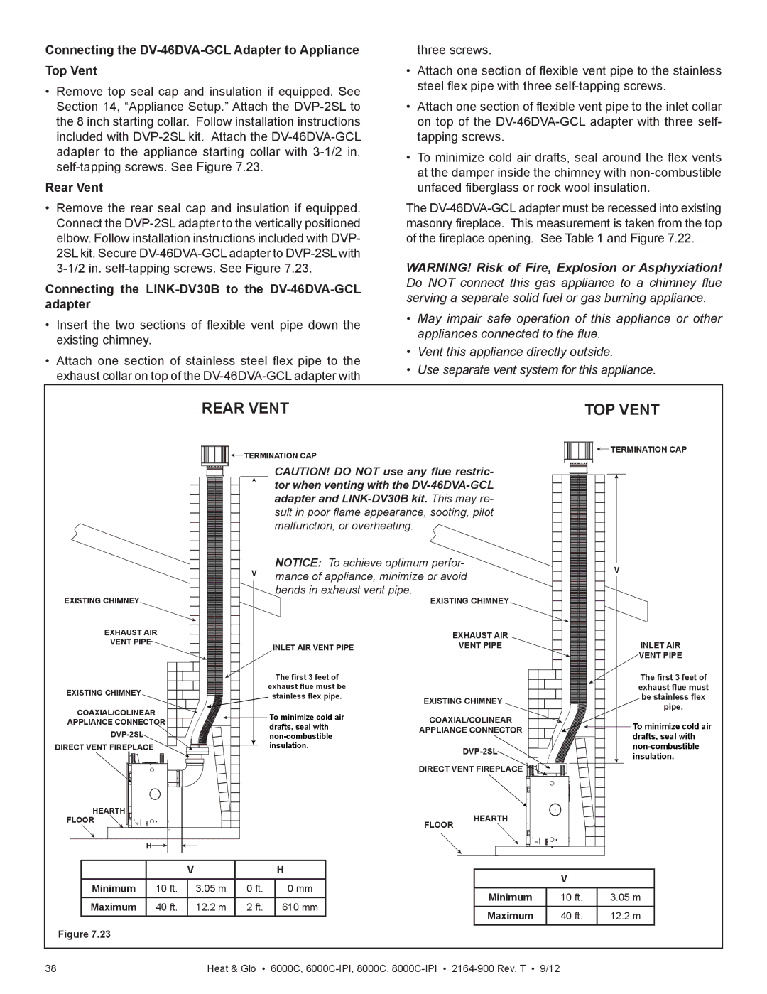
Connecting the DV-46DVA-GCL Adapter to Appliance Top Vent
•Remove top seal cap and insulation if equipped. See Section 14, “Appliance Setup.” Attach the
Rear Vent
•Remove the rear seal cap and insulation if equipped. Connect the
Connecting the LINK-DV30B to the DV-46DVA-GCL adapter
•Insert the two sections of flexible vent pipe down the existing chimney.
•Attach one section of stainless steel flex pipe to the exhaust collar on top of the
three screws.
•Attach one section of flexible vent pipe to the stainless steel flex pipe with three
•Attach one section of flexible vent pipe to the inlet collar on top of the
•To minimize cold air drafts, seal around the flex vents at the damper inside the chimney with
The
WARNING! Risk of Fire, Explosion or Asphyxiation! Do NOT connect this gas appliance to a chimney flue serving a separate solid fuel or gas burning appliance.
•May impair safe operation of this appliance or other appliances connected to the flue.
•Vent this appliance directly outside.
•Use separate vent system for this appliance.
REAR VENT | TOP VENT |
![]()
![]()
![]()
![]()
![]()
![]()
![]() TERMINATION CAP
TERMINATION CAP
| CAUTION! DO NOT use any flue restric- | |||
| tor when venting with the | |||
| adapter and | |||
| sult in poor flame appearance, sooting, pilot | |||
| malfunction, or overheating. |
|
| |
V | NOTICE: To achieve optimum perfor- |
| ||
mance of appliance, minimize or avoid |
| |||
EXISTING CHIMNEY | bends in exhaust vent pipe. | EXISTING CHIMNEY | ||
| ||||
EXHAUST AIR |
| EXHAUST AIR | ||
VENT PIPE | INLET AIR VENT PIPE | VENT PIPE | ||
| ||||
| The first 3 feet of |
|
| |
EXISTING CHIMNEY | exhaust flue must be |
|
| |
stainless flex pipe. | EXISTING CHIMNEY | |||
| ||||
|
| |||
COAXIAL/COLINEAR | To minimize cold air | COAXIAL/COLINEAR | ||
APPLIANCE CONNECTOR | ||||
drafts, seal with | APPLIANCE CONNECTOR | |||
|
| |||
DIRECT VENT FIREPLACE | insulation. | |||
|
| |||
|
| DIRECT VENT FIREPLACE | ||
HEARTH |
|
| HEARTH | |
FLOOR |
| FLOOR | ||
|
|
| ||
H |
|
|
| |


 TERMINATION CAP
V
INLET AIR
VENT PIPE
The first 3 feet of exhaust flue must be stainless flex pipe.
![]()
![]()
![]()
![]()
![]() To minimize cold air
To minimize cold air
drafts, seal with
|
| V |
| H |
Minimum | 10 ft. | 3.05 m | 0 ft. | 0 mm |
Maximum | 40 ft. | 12.2 m | 2 ft. | 610 mm |
Figure 7.23
V
Minimum | 10 ft. | 3.05 m |
Maximum | 40 ft. | 12.2 m |
38 | Heat & Glo • 6000C, |
