C |
|
| F |
|
|
| |
V |
|
|
|
J | B |
|
|
| B |
| |
| V | B | |
| V | ||
| D | ||
| V | G | |
|
| V | M |
|
| A | V |
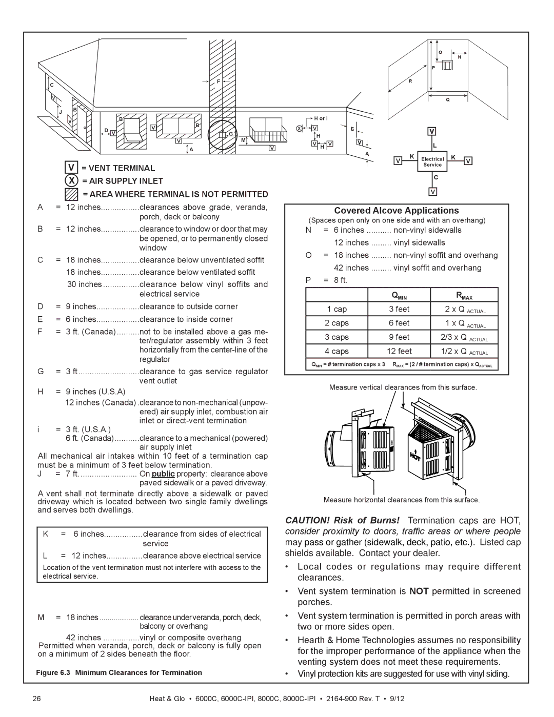
V= VENT TERMINAL X = AIR SUPPLY INLET
= AREA WHERE TERMINAL IS NOT PERMITTED
X
![]() H or i
H or i
![]()
![]()
![]()
![]() V
V
H
V ![]() H
H![]()
![]() V
V
E
V![]()
A
O
N
P
R
Q
|
| V |
|
| |
|
|
| L |
|
|
V | K | Electrical | K | V | |
|
| Service |
|
| |
|
|
|
|
|
|
C
V
A | = | 12 inches | clearances above grade, veranda, |
|
|
| porch, deck or balcony |
B | = 12 inches | clearance to window or door that may | |
|
|
| be opened, or to permanently closed |
|
|
| window |
C | = | 18 inches | clearance below unventilated soffit |
|
| 18 inches | clearance below ventilated soffit |
|
| 30 inches | clearance below vinyl soffits and |
|
|
| electrical service |
D | = | 9 inches | clearance to outside corner |
E | = | 6 inches | clearance to inside corner |
F | = | 3 ft. (Canada) | not to be installed above a gas me- |
|
|
| ter/regulator assembly within 3 feet |
|
|
| horizontally from the |
|
|
| regulator |
G | = | 3 ft | clearance to gas service regulator |
|
|
| vent outlet |
H= 9 inches (U.S.A)
12inches (Canada) .clearance to
i = 3 ft. (U.S.A.)
6 ft. (Canada) | ...........clearance to a mechanical (powered) |
| air supply inlet |
All mechanical air intakes within 10 feet of a termination cap must be a minimum of 3 feet below termination.
J | = 7 ft | On public property: clearance above |
|
| paved sidewalk or a paved driveway. |
A vent shall not terminate directly above a sidewalk or paved driveway which is located between two single family dwellings and serves both dwellings.
K | = | 6 inches | clearance from sides of electrical |
|
|
| service |
L | = | 12 inches | clearance above electrical service |
Location of the vent termination must not interfere with access to the electrical service.
M = 18 inches | clearanceunderveranda,porch,deck, |
| balcony or overhang |
42 inches | vinyl or composite overhang |
Permitted when veranda, porch, deck or balcony is fully open on a minimum of 2 sides beneath the floor.
Figure 6.3 Minimum Clearances for Termination
Covered Alcove Applications
(Spaces open only on one side and with an overhang)
N= 6 inches ...........
12 inches | vinyl sidewalls |
O= 18 inches .........
42 inches | ......... vinyl soffit and overhang | ||
P = 8 ft. |
|
| |
|
|
|
|
|
| QMIN | RMAX |
1 cap |
| 3 feet | 2 x Q ACTUAL |
2 caps |
| 6 feet | 1 x Q ACTUAL |
3 caps |
| 9 feet | 2/3 x Q ACTUAL |
4 caps |
| 12 feet | 1/2 x Q ACTUAL |
|
|
|
|
QMIN = # termination caps x 3 RMAX = (2 / # termination caps) x QACTUAL
Measure vertical clearances from this surface.
Measure horizontal clearances from this surface.
CAUTION! Risk of Burns! Termination caps are HOT, consider proximity to doors, traffic areas or where people may pass or gather (sidewalk, deck, patio, etc.). Listed cap shields available. Contact your dealer.
•Local codes or regulations may require different clearances.
•Vent system termination is NOT permitted in screened porches.
•Vent system termination is permitted in porch areas with two or more sides open.
•Hearth & Home Technologies assumes no responsibility for the improper performance of the appliance when the venting system does not meet these requirements.
•Vinyl protection kits are suggested for use with vinyl siding.
26 | Heat & Glo • 6000C, |