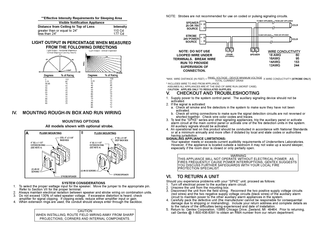
SPKE4, SPKE8 specifications
Gentek SPKE4 and SPKE8 are advanced network devices designed for high-performance communication and connectivity in modern networking environments. These models stand out for their robust features, enhanced capabilities, and support for cutting-edge technologies, catering to both enterprise and consumer demands.One of the key features of the Gentek SPKE4 and SPKE8 is their exceptional speed and efficiency. These devices support high data transfer rates, making them ideal for applications that require rapid communication, such as streaming, gaming, and cloud-based services. With capabilities that often exceed standard Ethernet connections, users can enjoy seamless connectivity without the bottlenecks that typically affect older technology.
Moreover, both models are equipped with advanced routing protocols and management software that allow for easy integration into existing network architectures. This flexibility is essential for businesses looking to expand their network infrastructure without incurring excessive downtime or costs. The SPKE4 and SPKE8 can be configured to prioritize traffic, ensuring that critical applications maintain optimal performance even during peak usage times.
Security is also a paramount concern for network devices, and Gentek addresses this with robust security measures built into the SPKE4 and SPKE8. Both models feature advanced encryption standards and firewalls that protect against unauthorized access and potential threats. This focus on security helps organizations maintain compliance with regulations while safeguarding sensitive data.
Another significant characteristic of the SPKE4 and SPKE8 is their scalability. These devices are designed to grow with the changing needs of a business or home network. Whether it's adding more users, devices, or services, Gentek’s products ensure that expansion is straightforward and efficient, avoiding the complexities often associated with upgrading network infrastructure.
In terms of build quality, the SPKE4 and SPKE8 exhibit a compact yet durable design that makes them suitable for various environments, from small offices to larger enterprise settings. The intuitive user interface simplifies management and monitoring, allowing users to manage their network effortlessly.
Overall, Gentek SPKE4 and SPKE8 devices represent a perfect blend of performance, security, and user-friendly features, making them excellent choices for anyone seeking reliable and efficient networking solutions. Their technological advancements and characteristics ensure that users can meet the demands of today's digital landscape while gearing up for the future of connectivity.

