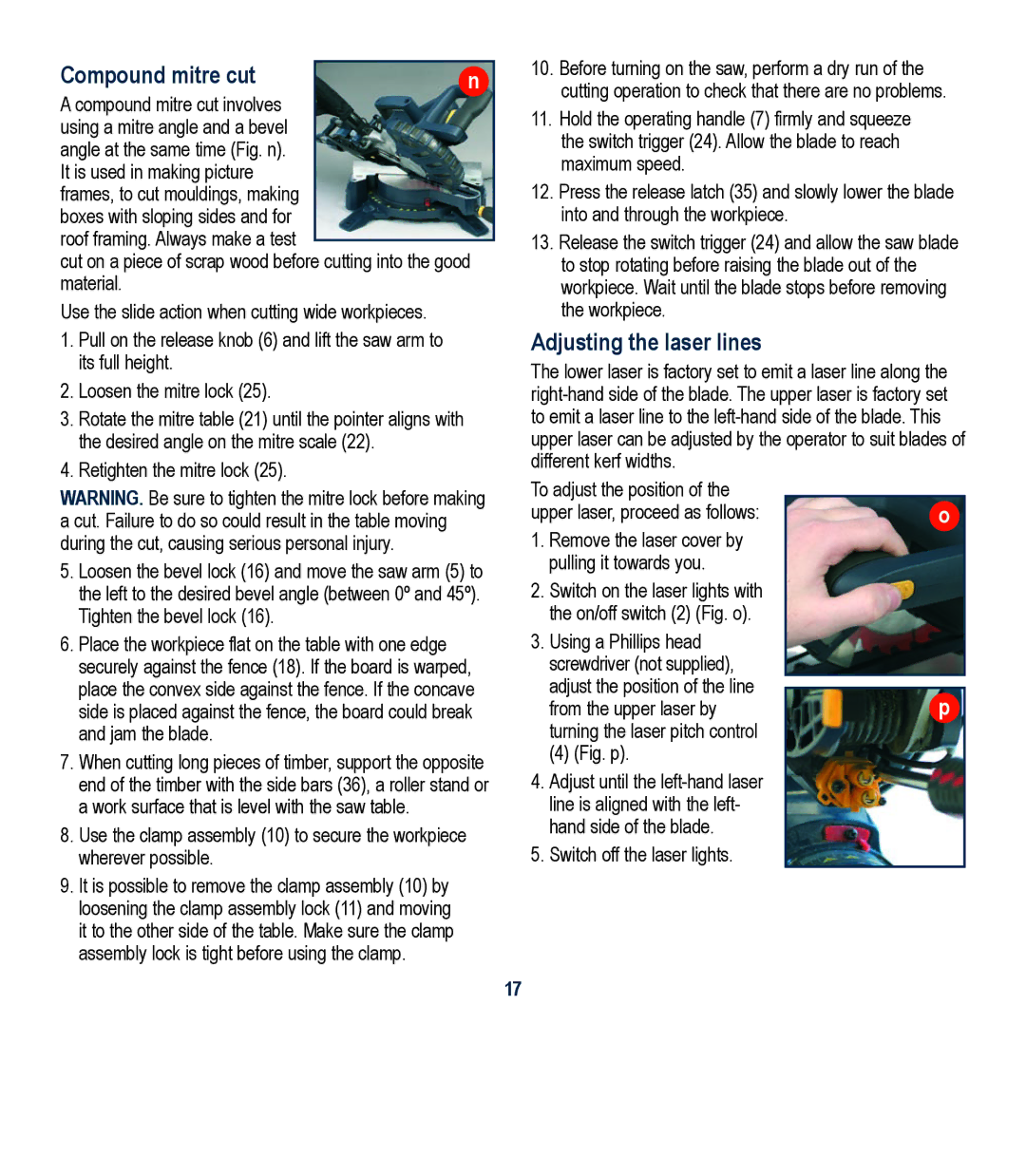
Compound mitre cut | n |
A compound mitre cut involves using a mitre angle and a bevel angle at the same time (Fig. n). It is used in making picture frames, to cut mouldings, making boxes with sloping sides and for roof framing. Always make a test
cut on a piece of scrap wood before cutting into the good material.
Use the slide action when cutting wide workpieces.
1.Pull on the release knob (6) and lift the saw arm to its full height.
2.Loosen the mitre lock (25).
3.Rotate the mitre table (21) until the pointer aligns with the desired angle on the mitre scale (22).
4.Retighten the mitre lock (25).
WARNING. Be sure to tighten the mitre lock before making a cut. Failure to do so could result in the table moving during the cut, causing serious personal injury.
5.Loosen the bevel lock (16) and move the saw arm (5) to the left to the desired bevel angle (between 0º and 45º). Tighten the bevel lock (16).
6.Place the workpiece flat on the table with one edge securely against the fence (18). If the board is warped, place the convex side against the fence. If the concave side is placed against the fence, the board could break and jam the blade.
7.When cutting long pieces of timber, support the opposite end of the timber with the side bars (36), a roller stand or a work surface that is level with the saw table.
8.Use the clamp assembly (10) to secure the workpiece wherever possible.
9.It is possible to remove the clamp assembly (10) by loosening the clamp assembly lock (11) and moving it to the other side of the table. Make sure the clamp assembly lock is tight before using the clamp.
10.Before turning on the saw, perform a dry run of the cutting operation to check that there are no problems.
11.Hold the operating handle (7) firmly and squeeze
the switch trigger (24). Allow the blade to reach maximum speed.
12.Press the release latch (35) and slowly lower the blade into and through the workpiece.
13.Release the switch trigger (24) and allow the saw blade to stop rotating before raising the blade out of the workpiece. Wait until the blade stops before removing the workpiece.
Adjusting the laser lines
The lower laser is factory set to emit a laser line along the
To adjust the position of the |
|
upper laser, proceed as follows: | o |
1.Remove the laser cover by pulling it towards you.
2.Switch on the laser lights with the on/off switch (2) (Fig. o).
3.Using a Phillips head screwdriver (not supplied),
adjust the position of the line
from the upper laser byp turning the laser pitch control
(4) (Fig. p).
4.Adjust until the left-hand laser line is aligned with the left- hand side of the blade.
5.Switch off the laser lights.
17