Know your product
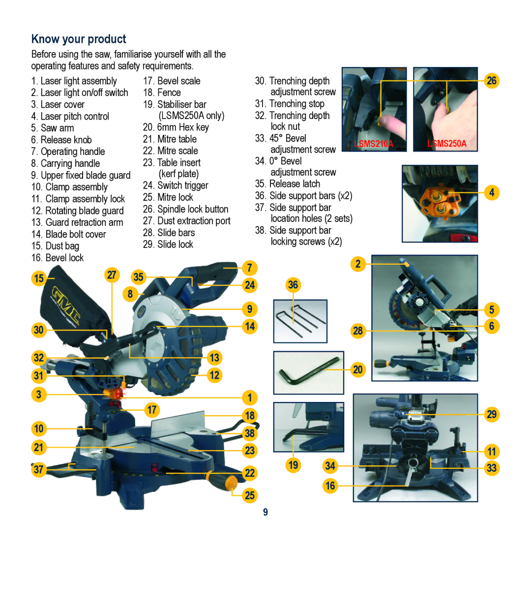
Before using the saw, familiarise yourself with all the operating features and safety requirements.
1. | Laser light assembly | 17. | Bevel scale | |||||||
2. | Laser light on/off switch | 18. | Fence | |||||||
3. | Laser cover | 19. | Stabiliser bar | |||||||
4. | Laser pitch control |
|
| (LSMS250A only) | ||||||
5. Saw arm | 20. | 6mm Hex key | ||||||||
6. | Release knob | 21. | Mitre table | |||||||
7. | Operating handle | 22. | Mitre scale | |||||||
8. | Carrying handle | 23. | Table insert | |||||||
9. | Upper fixed blade guard |
|
| (kerf plate) | ||||||
10. | Clamp assembly | 24. | Switch trigger | |||||||
11. Clamp assembly lock | 25. | Mitre lock | ||||||||
12. | Rotating blade guard | 26. | Spindle lock button | |||||||
13. | Guard retraction arm | 27. | Dust extraction port | |||||||
14. | Blade bolt cover | 28. | Slide bars | |||||||
15. | Dust bag | 29. | Slide lock | |||||||
16. | Bevel lock |
|
|
|
| |||||
15 |
| 27 |
|
| 35 |
|
|
| ||
|
|
|
|
|
| |||||
30 | 8 |
|
| 13 | ||||||
|
|
|
|
|
|
| ||||
|
|
|
|
|
|
| ||||
32 |
|
|
|
|
|
|
| |||
|
|
|
|
|
|
| ||||
|
|
|
|
|
|
| ||||
|
|
|
|
|
|
| ||||
31 |
|
|
|
|
|
|
| 12 | ||
|
|
|
|
|
|
| ||||
3 |
|
|
|
|
|
|
|
|
| |
17
10
21
37
7
24
9
14
1
18
38
23
22
25
30.Trenching depth adjustment screw
31.Trenching stop
32.Trenching depth lock nut
33. 45° Bevel | LSMS210A | LSMS250A | |
adjustment screw | |||
|
| ||
|
|
34.0° Bevel adjustment screw
35.Release latch
36.Side support bars (x2)
37.Side support bar location holes (2 sets)
38.Side support bar locking screws (x2)
2
36
28
20
1934
16
26
4
5
6
29
11
33
9