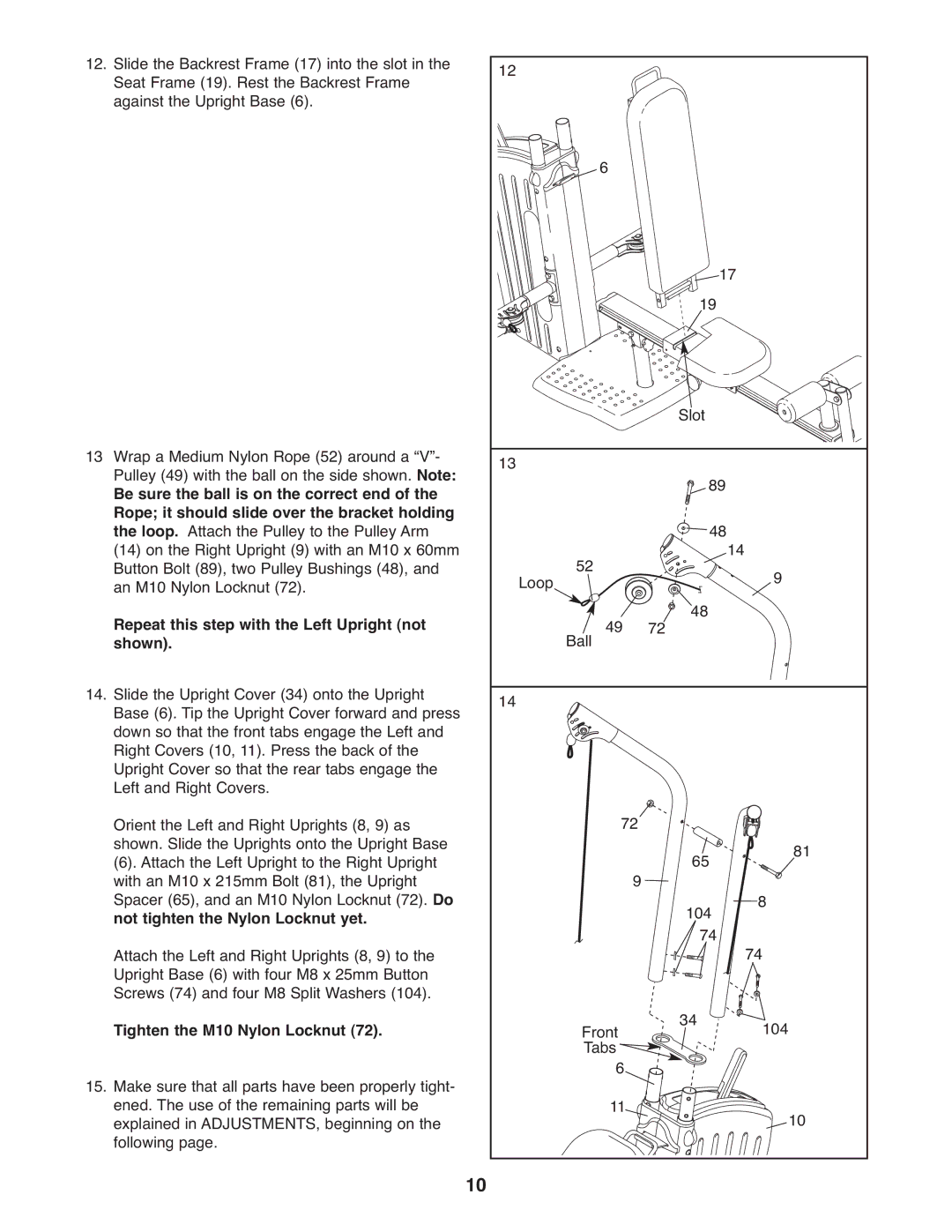
12. | Slide the Backrest Frame (17) into the slot in the | 12 |
|
|
|
|
|
|
| Seat Frame (19). Rest the Backrest Frame |
|
|
|
|
|
| |
| against the Upright Base (6). |
|
|
|
|
|
|
|
|
|
|
| 6 |
|
|
|
|
|
|
|
|
|
| 19 17 |
| |
13 | Wrap a Medium Nylon Rope (52) around a “V”- |
|
|
|
| Slot |
|
|
13 |
|
|
|
|
|
| ||
| Pulley (49) with the ball on the side shown. Note: |
|
|
| 89 |
|
| |
| Be sure the ball is on the correct end of the |
|
|
|
|
|
| |
| Rope; it should slide over the bracket holding |
|
|
|
| 48 |
|
|
| the loop. Attach the Pulley to the Pulley Arm |
|
|
|
| 14 |
| |
| (14) on the Right Upright (9) with an M10 x 60mm |
| 52 |
|
|
|
| |
| Button Bolt (89), two Pulley Bushings (48), and | Loop |
|
|
|
| 9 | |
| an M10 Nylon Locknut (72). |
|
|
| 48 |
| ||
| Repeat this step with the Left Upright (not |
| Ball | 49 | 72 |
|
| |
| shown). |
|
|
|
|
|
| |
14. | Slide the Upright Cover (34) onto the Upright | 14 |
|
|
|
|
|
|
| Base (6). Tip the Upright Cover forward and press |
|
|
|
|
|
| |
| down so that the front tabs engage the Left and |
|
|
|
|
|
|
|
| Right Covers (10, 11). Press the back of the |
|
|
|
|
|
|
|
| Upright Cover so that the rear tabs engage the |
|
|
|
|
|
|
|
| Left and Right Covers. |
|
| 72 |
|
|
|
|
| Orient the Left and Right Uprights (8, 9) as |
|
|
|
|
|
| |
| shown. Slide the Uprights onto the Upright Base |
|
|
|
| 65 |
| 81 |
| (6). Attach the Left Upright to the Right Upright |
|
| 9 |
|
| ||
| with an M10 x 215mm Bolt (81), the Upright |
|
|
|
|
|
| |
| Spacer (65), and an M10 Nylon Locknut (72). Do |
|
|
|
| 104 |
| 8 |
| not tighten the Nylon Locknut yet. |
|
|
|
|
| ||
| Attach the Left and Right Uprights (8, 9) to the |
|
|
|
| 74 |
| 74 |
| Upright Base (6) with four M8 x 25mm Button |
|
|
|
|
|
|
|
| Screws (74) and four M8 Split Washers (104). |
|
|
|
| 34 |
| 104 |
| Tighten the M10 Nylon Locknut (72). |
| Front |
|
| |||
15. | Make sure that all parts have been properly tight- |
| Tabs6 |
|
|
|
| |
| ened. The use of the remaining parts will be |
|
| 11 |
|
|
| 10 |
| explained in ADJUSTMENTS, beginning on the |
|
|
|
|
|
| |
| following page. | 10 |
|
|
|
|
|
|
|
|
|
|
|
|
|
| |
