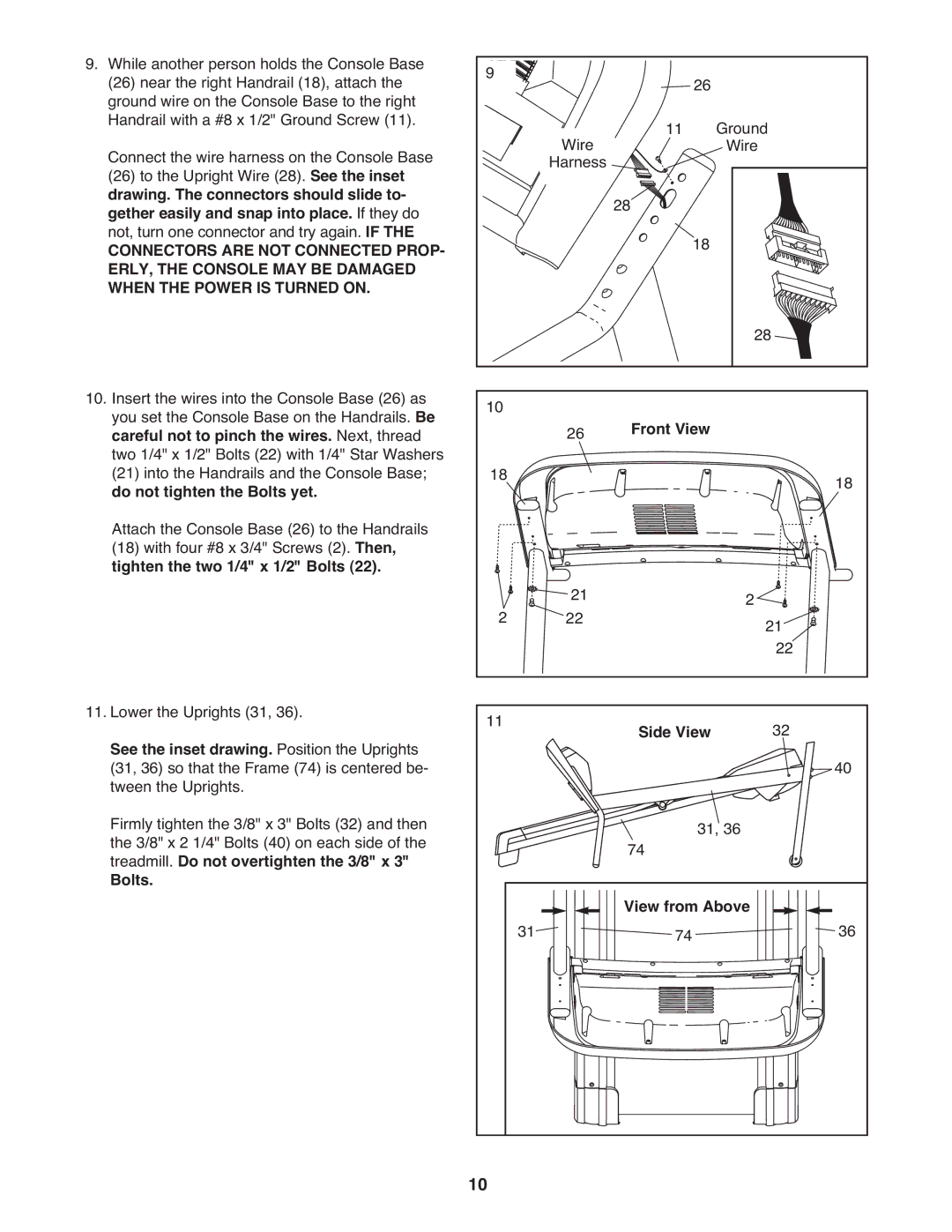
9.While another person holds the Console Base (26) near the right Handrail (18), attach the ground wire on the Console Base to the right Handrail with a #8 x 1/2" Ground Screw (11).
Connect the wire harness on the Console Base (26) to the Upright Wire (28). See the inset drawing. The connectors should slide to- gether easily and snap into place. If they do not, turn one connector and try again. IF THE
CONNECTORS ARE NOT CONNECTED PROP- ERLY, THE CONSOLE MAY BE DAMAGED WHEN THE POWER IS TURNED ON.
10. Insert the wires into the Console Base (26) as you set the Console Base on the Handrails. Be careful not to pinch the wires. Next, thread two 1/4" x 1/2" Bolts (22) with 1/4" Star Washers (21) into the Handrails and the Console Base; do not tighten the Bolts yet.
Attach the Console Base (26) to the Handrails (18) with four #8 x 3/4" Screws (2). Then, tighten the two 1/4" x 1/2" Bolts (22).
11. Lower the Uprights (31, 36).
See the inset drawing. Position the Uprights (31, 36) so that the Frame (74) is centered be- tween the Uprights.
Firmly tighten the 3/8" x 3" Bolts (32) and then the 3/8" x 2 1/4" Bolts (40) on each side of the treadmill. Do not overtighten the 3/8" x 3"
Bolts.
9 |
| 26 |
Wire | 11 | Ground |
| Wire | |
Harness | 28 |
|
| 18 | |
|
| |
|
| 28 |
10 | 26 | Front View |
| ||
18 | 18 | ||||
|
|
| |||
2 | 21 |
| 2 | 21 | |
22 |
| ||||
|
|
|
| 22 | |
11 |
| Side View | 32 | ||
|
|
|
| 40 | |
|
| 74 | 31, 36 |
| |
|
|
|
| ||
31 | View from Above | 36 |
74 |
10