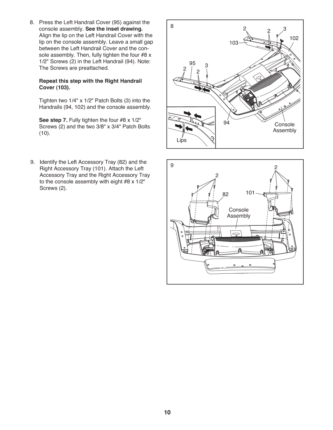
8. Press the Left Handrail Cover (95) against the |
| 8 |
| ||
console assembly. See the inset drawing. |
| |
Align the lip on the Left Handrail Cover with the |
|
|
lip on the console assembly. Leave a small gap |
|
|
between the Left Handrail Cover and the con- |
|
|
sole assembly. Then, fully tighten the four #8 x |
|
|
1/2" Screws (2) in the Left Handrail (94). Note: |
|
|
The Screws are preattached. |
|
|
Repeat this step with the Right Handrail |
|
|
Cover (103). |
|
|
Tighten two 1/4" x 1/2" Patch Bolts (3) into the |
|
|
Handrails (94, 102) and the console assembly. |
|
|
See step 7. Fully tighten the four #8 x 1/2" |
|
|
Screws (2) and the two 3/8" x 3/4" Patch Bolts |
|
|
(10). |
|
|
|
|
|
2 | 2 | 3 | 102 |
103 |
|
| |
|
|
|
2 | 95 2 | 3 |
94 | Console |
Lips | Assembly |
|
9.Identify the Left Accessory Tray (82) and the Right Accessory Tray (101). Attach the Left Accessory Tray and the Right Accessory Tray to the console assembly with eight #8 x 1/2" Screws (2).
9 | 2 | 2 |
| 101 | |
| 82 | |
|
| Console |
| Assembly | |
10
