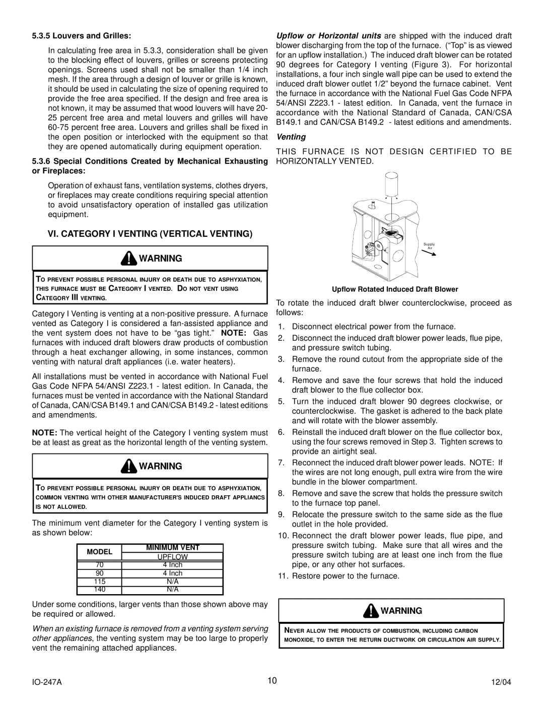
AMV8 specifications
Goodman Manufacturing has long been recognized as a key player in the HVAC industry, and the Goodman AMV8 stands out as a remarkable addition to their lineup of high-efficiency air conditioning units. Designed with the latest technological advancements, the AMV8 focuses on providing enhanced performance, energy efficiency, and reliability, making it a popular choice among homeowners and contractors alike.One of the primary features of the Goodman AMV8 is its high SEER (Seasonal Energy Efficiency Ratio) rating, which typically reaches up to 16 SEER. This impressive rating signifies that the unit is capable of delivering substantial energy savings compared to older models. By using less electricity to cool your home, the AMV8 not only impacts utility bills positively but also contributes to reducing your carbon footprint.
The Goodman AMV8 is built with a powerful and efficient scroll compressor, known for its ability to operate quietly while maintaining a smooth and reliable performance. The advanced design minimizes vibration, ensuring a quieter operation, which is particularly appealing for residential settings. Additionally, the unit features a multi-speed ECM blower motor that enhances airflow consistency and operational efficiency.
Construction quality is also noteworthy with the Goodman AMV8. The cabinet is made of durable galvanized steel, coated with a corrosion-resistant finish that protects against rust and weather-related wear and tear. This durability extends the lifespan of the unit and provides assurance of quality to consumers.
Another characteristic that elevates the AMV8 is its integrated comfort control system. This feature allows users to easily manage cooling settings, ensuring optimal comfort throughout the home. The intelligent design of the unit includes a communicator control board, which optimizes system performance and simplifies installation.
The Goodman AMV8 also incorporates environmentally conscious technologies, including the use of R-410A refrigerant. This refrigerant is known for its efficiency and lack of ozone depletion potential, aligning with standards for environmentally friendly HVAC options.
In summary, the Goodman AMV8 is a high-efficiency air conditioning unit that showcases impressive features such as a high SEER rating, a reliable scroll compressor, a durable exterior, and advanced comfort control capabilities. Its commitment to energy efficiency and environmental consideration make it an exemplary choice for those seeking a dependable and cost-effective cooling solution for their homes. Whether for new installations or replacements, the AMV8 stands as a testament to Goodman Manufacturing's dedication to quality and innovation in HVAC technology.

