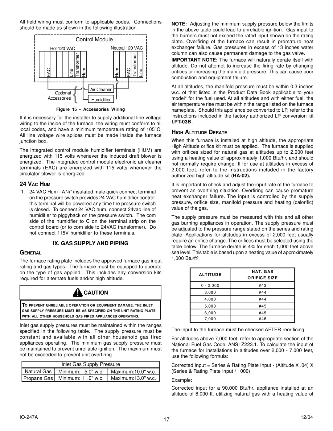
All field wiring must conform to applicable codes. Connections should be made as shown in the following illustration.

Control Module

NOTE: Adjusting the minimum supply pressure below the limits in the above table could lead to unreliable ignition. Gas input to the burners must not exceed the rated input shown on the rating plate. Overfiring of the furnace can result in premature heat

Hot 120 VAC

EAC


Line

Transformer

Optional { Accessories

Neutral 120 VAC

Hum

Hum


EAC

Transformer

Line


Air Cleaner

Humidifier

exchanger failure. Gas pressures in excess of 13 inches water column can also cause permanent damage to the gas valve.

IMPORTANT NOTE: The furnace will naturally derate itself with altitude. Do not attempt to increase the firing rate by changing orifices or increasing the manifold pressure. This can cause poor combustion and equipment failure.

At all altitudes, the manifold pressure must be within 0.3 inches w.c. of that listed in the Product Data Book applicable to your model* for the fuel used. At all altitudes and with either fuel, the air temperature rise must be within the range listed on the furnace

Figure 15 - Accessories Wiring

If it is necessary for the installer to supply additional line voltage wiring to the inside of the furnace, the wiring must conform to all local codes, and have a minimum temperature rating of 105°C. All line voltage wire splices must be made inside the furnace junction box.

The integrated control module humidifier terminals (HUM) are energized with 115 volts whenever the induced draft blower is energized. The integrated control module electronic air cleaner terminals (EAC) are energized with 115 volts whenever the circulator blower is energized.

24 VAC HUM

1.24 VAC Hum - A ¼” insulated male quick connect terminal on the pressure switch provides 24 VAC humidifier control. this terminal will be powered any time the pressure switch is closed. To connect 24 VAC hum, connect 24vac line of humidifier to piggyback on the pressure switch. The com side of the humidfier to C on the terminal strip on the control board (or to com side to 24VAC transformer). Do not connect 115V humidifier to these terminals.

IX. GAS SUPPLY AND PIPING

GENERAL

The furnace rating plate includes the approved furnace gas input rating and gas types. The furnace must be equipped to operate on the type of gas applied. This includes any conversion kits required for alternate fuels and/or high altitude.

CAUTION

TO PREVENT UNRELIABLE OPERATION OR EQUIPMENT DAMAGE, THE INLET GAS SUPPLY PRESSURE MUST BE AS SPECIFIED ON THE UNIT RATING PLATE WITH ALL OTHER HOUSEHOLD GAS FIRED APPLIANCES OPERATING.

Inlet gas supply pressures must be maintained within the ranges specified in the following table. The supply pressure must be constant and available with all other household gas fired appliances operating. The minimum gas supply pressure must be maintained to prevent unreliable ignition. The maximum must not be exceeded to prevent unit overfiring.

Inlet Gas Supply Pressure

Natural Gas

Minimum: 5.0" w.c.

Maximum:10.0" w.c.

Propane Gas

Minimum: 11.0" w.c.

Maximum:13.0" w.c.

nameplate. Should this appliance be converted to LP, refer to the instructions included in the factory authorized LP conversion kit LPT-03B .

HIGH ALTITUDE DERATE

When this furnace is installed at high altitude, the appropriate High Altitude orifice kit must be applied. The furnace is supplied with orifices sized for natural gas at altitudes up to 2,000 feet using a heating value of approximately 1,000 Btu/hr, and should not normally require change. If for use at altitudes in excess of 2,000 feet, refer to the instructions included in the factory authorized high altitude kit (HA-02).

It is important to check and adjust the input rate of the furnace to prevent an overfiring situation. Overfiring can cause premature heat exchanger failure. The input is controlled by the supply pressure, orifice size, manifold pressure and heating (calorific) value of the gas.

The supply pressure must be measured with this and all other gas burning appliances in operation. The supply pressure must be adjusted to the pressure range stated on the series and rating plate. Applications for altitudes in excess of 2,000 feet usually require an orifice change. The orifices must be selected using the table below. The furnace derate is 4% for each 1,000 feet above sea level. This table is based upon a heating value of approximately 1,000 Btu/ft3

ALTITUDE

NAT. GAS

ORIFICE SIZE


0 - 2,000

#43

3,000

#44

4,000

#44

5,000

#45

6,000

#45

7,000

#46


The input to the furnace must be checked AFTER reorificing.

For altitudes above 7,000 feet, refer to appropriate section of the National Fuel Gas Code, ANSI Z223.1. To calculate the input of the furnace for installations in altitudes over 2,000 - 7,000 feet, use the following formula:

Corrected Input = Series & Rating Plate Input - (Altitude X .04) X (Series & Rating Plate Input / 1000)

Example:

Corrected input for a 90,000 Btu/hr. appliance installed at an altitude of 6,000 ft. utilizing natural gas with a heating value of

IO-247A

17

12/04


Page 17
Image 17
Goodman Mfg AMV8 instruction manual IX. GAS Supply and Piping, High Altitude Derate, Altitude NAT. GAS Orifice Size

AMV8 specifications

Goodman Manufacturing has long been recognized as a key player in the HVAC industry, and the Goodman AMV8 stands out as a remarkable addition to their lineup of high-efficiency air conditioning units. Designed with the latest technological advancements, the AMV8 focuses on providing enhanced performance, energy efficiency, and reliability, making it a popular choice among homeowners and contractors alike.

One of the primary features of the Goodman AMV8 is its high SEER (Seasonal Energy Efficiency Ratio) rating, which typically reaches up to 16 SEER. This impressive rating signifies that the unit is capable of delivering substantial energy savings compared to older models. By using less electricity to cool your home, the AMV8 not only impacts utility bills positively but also contributes to reducing your carbon footprint.

The Goodman AMV8 is built with a powerful and efficient scroll compressor, known for its ability to operate quietly while maintaining a smooth and reliable performance. The advanced design minimizes vibration, ensuring a quieter operation, which is particularly appealing for residential settings. Additionally, the unit features a multi-speed ECM blower motor that enhances airflow consistency and operational efficiency.

Construction quality is also noteworthy with the Goodman AMV8. The cabinet is made of durable galvanized steel, coated with a corrosion-resistant finish that protects against rust and weather-related wear and tear. This durability extends the lifespan of the unit and provides assurance of quality to consumers.

Another characteristic that elevates the AMV8 is its integrated comfort control system. This feature allows users to easily manage cooling settings, ensuring optimal comfort throughout the home. The intelligent design of the unit includes a communicator control board, which optimizes system performance and simplifies installation.

The Goodman AMV8 also incorporates environmentally conscious technologies, including the use of R-410A refrigerant. This refrigerant is known for its efficiency and lack of ozone depletion potential, aligning with standards for environmentally friendly HVAC options.

In summary, the Goodman AMV8 is a high-efficiency air conditioning unit that showcases impressive features such as a high SEER rating, a reliable scroll compressor, a durable exterior, and advanced comfort control capabilities. Its commitment to energy efficiency and environmental consideration make it an exemplary choice for those seeking a dependable and cost-effective cooling solution for their homes. Whether for new installations or replacements, the AMV8 stands as a testament to Goodman Manufacturing's dedication to quality and innovation in HVAC technology.