Goodman Mfg AMV8 The selected speed must provide a temperature rise within, Heat Off Delay S

Models: AMV8

1 32
Download 32 pages 58.44 Kb
Page 25
Image 25
The selected speed must provide a temperature rise within


100% CFM

100% CFM

OFF

50% CFM

OFF


½ min

1 min


Cooling Demand


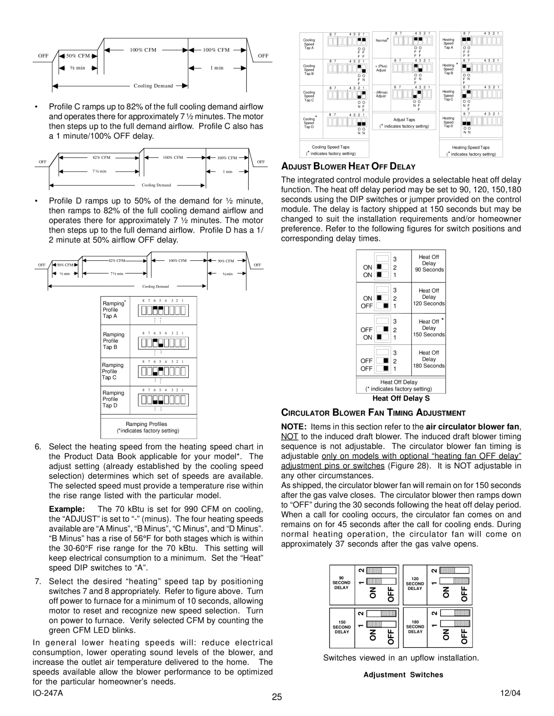
Profile C ramps up to 82% of the full cooling demand airflow and operates there for approximately 7 ½ minutes. The motor then steps up to the full demand airflow. Profile C also has a 1 minute/100% OFF delay.

82% CFM

100% CFM

100% CFM

OFF


OFF

7 ½ min


1 min

Cooling Demand

Profile D ramps up to 50% of the demand for ½ minute, then ramps to 82% of the full cooling demand airflow and operates there for approximately 7 ½ minutes. The motor then steps up to the full demand airflow. Profile D has a 1/ 2 minute at 50% airflow OFF delay.

OFF

50% CFM

82% CFM


100% CFM

50% CFM


OFF


½ min

7 ½ min


½ min


Cooling Demand


Ramping*

8

7

6


5

4

3

2

1


Profile


Tap A


O

O


F

F


F

F


Ramping

8

7

6


5

4

3

2

1


Profile


Tap B


O

O


F

N


F


Ramping

8

7

6


5

4

3

2

1


Profile


Tap C


O

O


N

F


F


Ramping

8

7

6


5

4

3

2

1


Profile


Tap D


O

O


N

N


Ramping Profiles (*indicates factory setting)

6. Select the heating speed from the heating speed chart in

the Product Data Book applicable for your model*. The

adjust setting (already established by the cooling speed

selection) determines which set of speeds are available.

The selected speed must provide a temperature rise within

the rise range listed with the particular model.

Example: The 70 kBtu is set for 990 CFM on cooling,

the “ADJUST” is set to “-” (minus). The four heating speeds

available are “A Minus”, “B Minus”, “C Minus”, and “D Minus”.

“B Minus” has a rise of 56°F for both stages which is within

the 30-60°F rise range for the 70 kBtu. This setting will

keep electrical consumption to a minimum. Set the “Heat”

speed DIP switches to “A”.


8

7


4

3

2

1


8

7

4

3

2

1


8

7

4

3

2

1


Normal*


Cooling


Heating


Speed


Speed


Tap A


O O


O O


Tap A

O O


F

F


F

F


F F


F

F


F

F


F F


8

7


4

3

2

1


8

7

4

3

2

1

Cooling


8

7

4

3

2

1


Heating *


+ (Plus)


Speed


Adjust


Speed


Tap B


O O


O O


Tap B

O

O


F N


F N


F N


F


F


F


Cooling


8

7

4

3

2

1


- (Minus)

8

7


4

3

2

1


Heating

8

7

4

3

2

1

Speed


Adjust


Speed


Tap C


O O


O O


Tap C

O O


N F


N F


N F


F


F


F


Cooling*


8

7

4

3

2

1


Heating

8

7

4

3

2

1


Adjust Taps


Speed


(* indicates factory setting)


Speed


Tap D


Tap D

O O


O O


N N


N N


Cooling Speed Taps


Heating Speed Taps


(* indicates factory setting)


(* indicates factory setting)


ADJUST BLOWER HEAT OFF DELAY

The integrated control module provides a selectable heat off delay function. The heat off delay period may be set to 90, 120, 150,180 seconds using the DIP switches or jumper provided on the control module. The delay is factory shipped at 150 seconds but may be changed to suit the installation requirements and/or homeowner preference. Refer to the following figures for switch positions and corresponding delay times.


3

Heat Off


Delay

ON


2


90 Seconds


ON


1

Heat Off


3


ON


2

Delay


OFF


1

120 Seconds


Heat Off *


3


OFF


2

Delay


ON


1

150 Seconds


Heat Off


3


OFF


2

Delay


OFF


1

180 Seconds


Heat Off Delay

(* indicates factory setting)

Heat Off Delay S

CIRCULATOR BLOWER FAN TIMING ADJUSTMENT

NOTE: Items in this section refer to the air circulator blower fan, NOT to the induced draft blower. The induced draft blower timing sequence is not adjustable. The circulator blower fan timing is adjustable only on models with optional “heating fan OFF delay” adjustment pins or switches (Figure 28). It is NOT adjustable in any other circumstances.

As shipped, the circulator blower fan will remain on for 150 seconds after the gas valve closes. The circulator blower then ramps down to “OFF” during the 30 seconds following the heat off delay period. When a call for cooling occurs, the circulator fan comes on and remains on for 45 seconds after the call for cooling ends. During normal heating operation, the circulator fan will come on approximately 37 seconds after the gas valve opens.

7. Select the desired “heating” speed tap by positioning

switches 7 and 8 appropriately. Refer to figure above. Turn

off power to furnace for a minimum of 10 seconds, allowing

motor to reset and recognize new speed selection. Turn

on power to furnace. Verify selected CFM by counting the

green CFM LED blinks.

In general lower heating speeds will: reduce electrical consumption, lower operating sound levels of the blower, and

90

SECOND DELAY

150 SECOND DELAY

2


1


2


1


120

SECOND DELAY

180

SECOND DELAY

2


1


NO


2


1


NO


increase the outlet air temperature delivered to the home. The speeds available allow the blower performance to be optimized for the particular homeowner’s needs.

Switches viewed in an upflow installation.

Adjustment Switches

IO-247A

25

12/04


Page 25
Image 25
Goodman Mfg AMV8 The selected speed must provide a temperature rise within, Heat Off Delay S, Adjustment Switches