MAIN POWER

LOW VOLTAGE

BLOCK

LOW VOLTAGE

ENTRANCE POWER THRU

THE CURB

CONTROL BOX

WARNING

FAILURE OF UNIT DUE TO OPERATION ON IMPROPER LINE VOLTAGE OR WITH EXCESSIVE PHASE UNBALANCE CONSTITUTES PRODUCT ABUSE AND WILL VOID YOUR WARRANTY AND MAY CAUSE SEVERE DAMAGE TO THE UNIT ELECTRICAL COMPONENTS.

Areas Without Convenience Outlet

It is recommended that an independent 115V power source be brought to the vicinity of the roof top unit for portable lights and tools used by the service mechanic.

UNITS INSTALLED ON ROOF TOPS

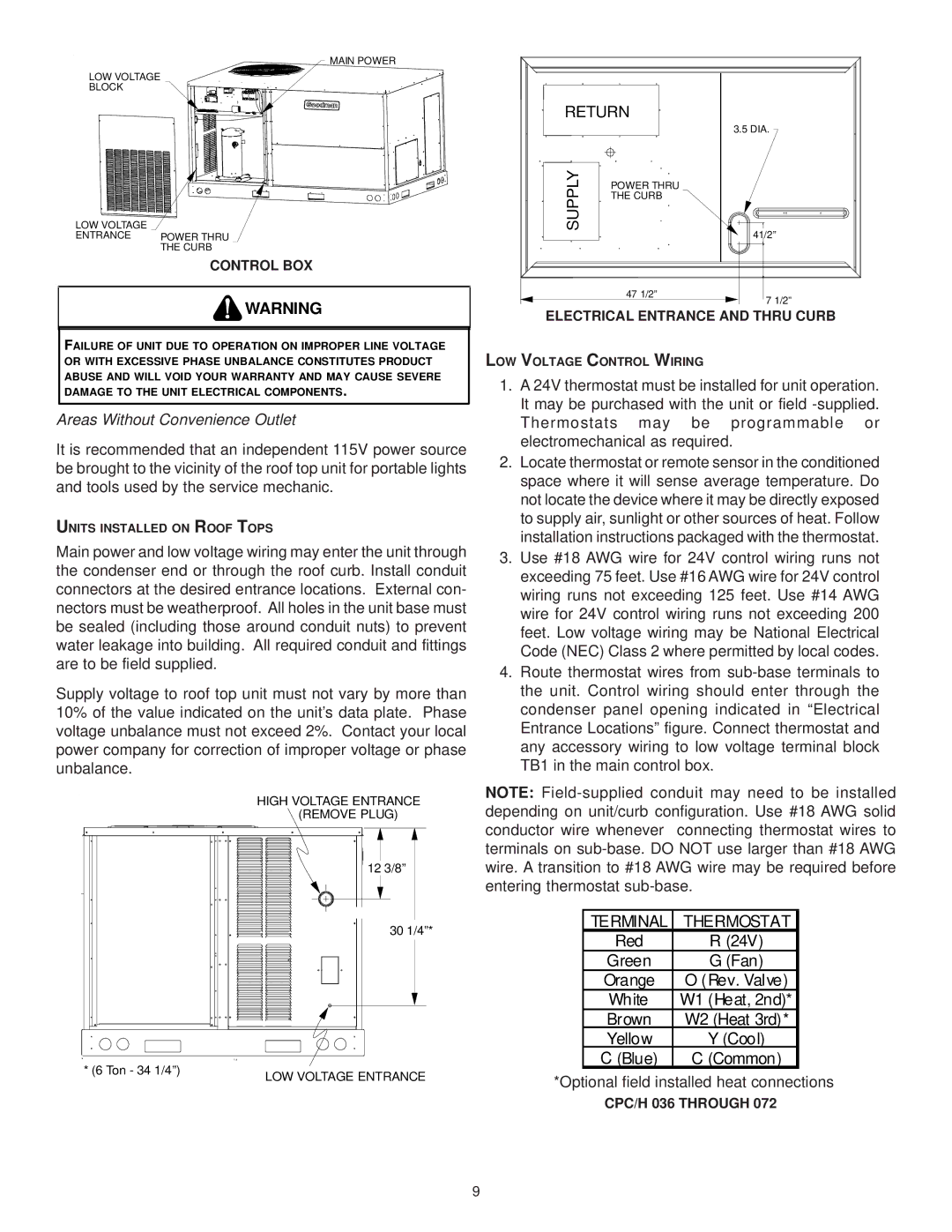
Main power and low voltage wiring may enter the unit through the condenser end or through the roof curb. Install conduit connectors at the desired entrance locations. External con- nectors must be weatherproof. All holes in the unit base must be sealed (including those around conduit nuts) to prevent water leakage into building. All required conduit and fittings are to be field supplied.

Supply voltage to roof top unit must not vary by more than 10% of the value indicated on the unit’s data plate. Phase voltage unbalance must not exceed 2%. Contact your local power company for correction of improper voltage or phase unbalance.

HIGH VOLTAGE ENTRANCE (REMOVE PLUG)


12 3/8”


30 1/4”*


1:4

* (6 Ton - 34 1/4”)

LOW VOLTAGE ENTRANCE


RETURN


3.5 DIA.

SUPPLY

POWER THRU


THE CURB


41/2”


47 1/2”

7 1/2”


ELECTRICAL ENTRANCE AND THRU CURB

LOW VOLTAGE CONTROL WIRING

1.A 24V thermostat must be installed for unit operation. It may be purchased with the unit or field -supplied. Thermostats may be programmable or electromechanical as required.

2.Locate thermostat or remote sensor in the conditioned space where it will sense average temperature. Do not locate the device where it may be directly exposed to supply air, sunlight or other sources of heat. Follow installation instructions packaged with the thermostat.

3.Use #18 AWG wire for 24V control wiring runs not exceeding 75 feet. Use #16 AWG wire for 24V control wiring runs not exceeding 125 feet. Use #14 AWG wire for 24V control wiring runs not exceeding 200 feet. Low voltage wiring may be National Electrical Code (NEC) Class 2 where permitted by local codes.

4.Route thermostat wires from sub-base terminals to the unit. Control wiring should enter through the condenser panel opening indicated in “Electrical Entrance Locations” figure. Connect thermostat and any accessory wiring to low voltage terminal block TB1 in the main control box.

NOTE: Field-supplied conduit may need to be installed depending on unit/curb configuration. Use #18 AWG solid conductor wire whenever connecting thermostat wires to terminals on sub-base. DO NOT use larger than #18 AWG wire. A transition to #18 AWG wire may be required before entering thermostat sub-base.

TERMINAL

THERMOSTAT

Red

R (24V)

Green

G (Fan)

Orange

O (Rev. Valve)

White

W1 (Heat, 2nd)*

Brown

W2 (Heat 3rd)*

Yellow

Y (Cool)

C (Blue)

C (Common)

*Optional field installed heat connections

CPC/H 036 THROUGH 072

9

Page 9
Image 9
Goodman Mfg IO-354B installation instructions Supply

IO-354B specifications

The Goodman Mfg IO-354B is a high-efficiency, residential air conditioning unit known for its robust performance and reliability. As a part of Goodman’s commitment to providing affordable and efficient HVAC solutions, the IO-354B stands out with its advanced features, durable construction, and user-friendly technologies.

One of the primary highlights of the IO-354B is its impressive cooling capacity, making it a perfect choice for medium to large-sized homes. With a cooling capacity of 3.5 tons, this unit efficiently maintains comfortable indoor temperatures even during the hottest summer days. It operates quietly, ensuring that homeowners can enjoy a peaceful environment without the disruption of loud mechanical noises.

The IO-354B incorporates advanced multi-speed fan technology, which not only enhances air circulation but also promotes energy efficiency. This feature allows the system to adjust its speed based on current cooling needs, reducing energy consumption while ensuring optimal comfort. This makes the unit not only cost-effective but also environmentally friendly, as it helps to lower the carbon footprint of the household.

Efficiency is a hallmark of the IO-354B, boasting a high SEER rating. A higher Seasonal Energy Efficiency Ratio (SEER) translates to better energy savings; thus, reducing overall utility bills. This efficiency is further enhanced by the unit’s use of eco-friendly refrigerants, contributing to a greener solution for air conditioning needs.

Durability is another critical characteristic of the Goodman IO-354B. Constructed with a heavy-duty, galvanized steel cabinet, it is built to withstand even the toughest weather conditions. Additionally, the unit features a high-performance scroll compressor, known for its longevity and fewer moving parts, which results in a more reliable operation over time.

Goodman also places a strong emphasis on ease of maintenance with the IO-354B. Its user-friendly design includes removable panels that facilitate access for routine service and maintenance, ensuring that homeowners can keep their systems in optimal condition without hassle.

In summary, the Goodman Mfg IO-354B combines high efficiency, durability, and innovative technology to deliver comfort and affordability. Whether seeking to cool down a new home or replace an aging unit, the IO-354B is an excellent choice for those prioritizing performance and energy savings in their HVAC system. With a rich history in the industry, Goodman continues to be a trusted name in heating and air conditioning, and the IO-354B exemplifies this commitment to quality and innovation.