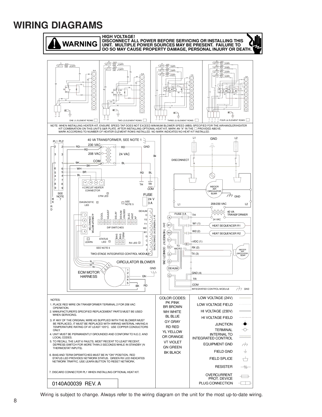
WIRING DIAGRAMS

HIGH VOLTAGE!

DISCONNECT ALL POWER BEFORE SERVICING OR INSTALLING THIS

UNIT. MULTIPLE POWER SOURCES MAY BE PRESENT. FAILURE TO

DO SO MAY CAUSE PROPERTY DAMAGE, PERSONAL INJURY OR DEATH.

FL

HTR1 TL

BK

PU

BK

BL

M1

R

M2

WH

BK

BK

RD

L1 L2

BK

RD

PLM

1

2

3

4

5

6

7

8

9


FL


FL

HTR2

TL


HTR1 TL


RD


BK

BK


PU


BL

RD


M1

M3


R

M4


M2


WH


RD


BK


BK


RD

BK

RD

PLM

1

2

3

4

5

6

7

8

9

FL

FL

HT R1

TL

B K


FL

HT R2 TL

RD


HT R3

TL


P LM


B K


1


RD


YL

P U

2

YL

B K


3


B L

RD


M1

M3

M1


BL

4

RD

M2

M4

M2


BK

R1

R2

BR

5

BK


RD


W H

6


7


Y L


8


BK


RD


9

FL


FL

H TR1 TL


B K


FL

H TR2 TL


R D


FL

H TR3 TL


Y L


H TR4 TL


BL


PLM


B K

1


P U


2

B L

BK

R D


3


B L


Y L

M1

M3

M5

M7

R D


BL

4


R D

M2

M4

M6

M8


B K

R1


R2

BR

5


B K

R D


W H

6


7


YL


B L


8


B K


R D


9

ONE (1) ELEMENT ROWS

L1

L2

TWO (2) ELEMENT ROWS


L 1 L 2 L 1 L2 THREE (3) ELEMENT ROWS

L1 L2 L1 L2 FOUR (4) ELEMENT ROWS

NOTE: WHEN INSTALLING HEATER KIT, ENSURE SPEED TAP DOES NOT EXCEED MINIMUM BLOWER SPEED (MBS) SPECIFIED FOR THE AIRHANDLER/HEATER KIT COMBINATION ON THIS UNIT'S S&R PLATE. AFTER INSTALLING OPTIONAL HEAT KIT, MARK AN "X" IN THE PROVIDED ABOVE.

MARK ACCORDING TO NUMBER OF HEATER ELEMENT ROWS INSTALLED. NO MARK INDICATES NO HEAT KIT INSTALLED.

PL1 PL2


2

2


3

3


1

1


6

6


5

5


4

4


7

7


8

8


9

9


SEE

NOTE

B- 7

K

R

D


40 VA TRANSFORMER, SEE NOTE 1


RD

230 VAC


RD

GND


RD


208 VAC


24 VAC


GN


BK

COM


BL


BK


WH


BR


RD

BL

BL


4

3

2

1


TH

TR

4 CIRCUIT HEATER


COM

CONNECTOR


CFM LED


FUSE

DIAGNOSTIC


SEE


24 V


3 A

LED


NOTE 5


COOL


ADJUST

DELAY DEHUM UNUSED ELEC HEAT AF


24V


DEHUM


1


O


2


BIAS BIAS TERM

Y2

THERMOSTATCONNECTIONS


2

3


Y1


DIP SWITCHES

W2


4


W1


STATUS


G


C


LEARN


LED


RX LED


R


SEE NOTE 6


TWO-STAGE INTEGRATED CONTROL MODULE1


GY


CIRCULATOR BLOWER


BL


BK


4


RD


2

3


1


GND

ECM MOTOR

1


2


HARNESS


3

GN


4


5

RD


BK


L1


GND

L2


DISCONNECT


INDOOR


AIR


CIRCULATOR


BLWR

GND


L1


208/230 VAC

L2


FUSE 3 A


40 VA


R

TH

TRANSFORMER


24 VAC


24V

W1


W1 (1)

HEAT SEQUENCER R1


THERMOSTAT

W2


W2 (2)

HEAT SEQUENCER R2


Y1


+VDC (1)


CONNECTIONS

Y2

TO

RX (2)


MICRO


INDOOR


G


TX (3)


AIR


CIRCULATOR


BLWR


O


DEHUM


C


GND (4)


TR


COM


INTEGRATED CONTROL MODULE

GND

NOTES:

1.PLACE RED WIRE ON TRANSFORMER TERMINAL 2 FOR 208 VAC OPERATION.

2.MANUFACTURER'S SPECIFIED REPLACEMENT PARTS MUST BE USED WHEN SERVICING.

3.IF ANY OF THE ORIGINAL WIRE AS SUPPLIED WITH THE BLOWER MUST BE REPLACED, IT MUST BE REPLACED WITH WIRING MATERIAL HAVING A TEMPERATURE RATING OF AT LEAST 105°C. USE COPPER CONDUCTORS ONLY.

4.UNIT MUST BE PERMANENTLY GROUNDED AND CONFORM TO N.E.C. AND LOCAL CODES.

5.TO RECALL THE LAST 6 FAULTS, MOST RECENT TO LEAST RECENT, DEPRESS SWITCH FOR MORE THAN 2 SECONDS WHILE IN STANDBY (N THERMOSTAT INPUTS).

6.BIAS AND TERM DIPSWITCHES MUST BE IN "ON" POSITION. RED STATUS LED PROVIDES NETWORK STATUS. GREEN RX LED INDICATES NETWORK TRAFFIC. USE LEARN BUTTON TO RESET NETWORK.

7.DISCARD CONNECTOR PL1 WHEN INSTALLING OPTIONAL HEAT KIT.

0140A00039 REV. A

COLOR CODES:

PK PINK

BR BROWN

WH WHITE

BL BLUE

GY GRAY

RD RED

YL YELLOW

OR ORANGE

VT VIOLET

GN GREEN

BK BLACK

LOW VOLTAGE (24V)

LOW VOLTAGE FIELD

HI VOLTAGE (230V)

HI VOLTAGE FIELD

JUNCTION

TERMINAL

INTERNAL TO INTEGRATED CONTROL

EQUIPMENT GND

FIELD GND

FIELD SPLICE

RESISTER

OVERCURRENT

PROT. DEVICE PLUG CONNECTION

Wiring is subject to change. Always refer to the wiring diagram on the unit for the most up-to-date wiring.

8

Page 8
Image 8
Goodman Mfg RT6223003 service manual 0140A00039 REV. a

RT6223003 specifications

The Goodman Mfg RT6223003 is a top-tier heat pump that is designed to provide both efficiency and comfort in residential heating and cooling applications. Known for its reliability and performance, this model is a popular choice among homeowners looking for an affordable yet effective climate control system.

One of the standout features of the RT6223003 is its SEER rating of up to 16, which highlights its energy efficiency. The higher the SEER rating, the more efficient the unit operates, translating into lower energy bills for homeowners. This model is built with a two-stage compressor that not only enhances comfort by minimizing temperature fluctuations but also contributes to increased efficiency during operation.

The RT6223003 utilizes advanced refrigerant technology, incorporating R-410A refrigerant. This eco-friendly refrigerant is less harmful to the ozone layer compared to older refrigerants such as R-22, making it a more sustainable choice for modern HVAC systems. The unit is also equipped with a smart and durable design that includes a robust galvanized steel cabinet with a UV-resistant powder finish to protect against the elements, ensuring longevity and performance.

Additionally, this model features a variable speed blower motor, which allows for precise airflow control and enhanced humidity regulation. This means that not only can the RT6223003 maintain the desired temperature, but it can also help to keep indoor air quality at optimal levels, which is crucial for overall comfort.

Installation and maintenance are designed to be straightforward with Goodman’s user-friendly features. The RT6223003 comes with a comprehensive warranty, typically offering a limited lifetime warranty on the compressor and a 10-year parts warranty, providing peace of mind for homeowners regarding their investment.

The unit's noise levels are kept in check thanks to its sound-dampening features. This means it operates quietly, making it suitable for residential areas without causing disturbance.

In summary, the Goodman Mfg RT6223003 heat pump is a perfect blend of efficiency, durability, and advanced technology, making it an excellent choice for homeowners seeking reliable and effective climate control solutions. With its impressive features and eco-friendly design, it accommodates the needs of modern living while promoting energy conservation.