Installation
Connections
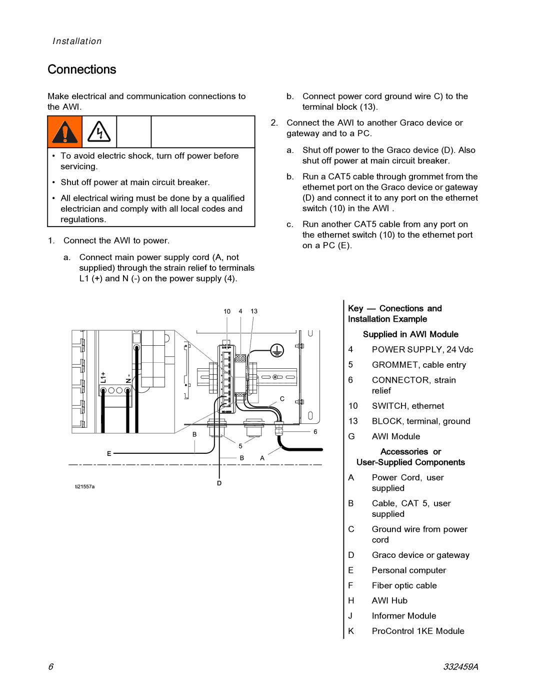
Make electrical and communication connections to the AWI.
•To avoid electric shock, turn off power before servicing.
•Shut off power at main circuit breaker.
•All electrical wiring must be done by a qualified electrician and comply with all local codes and regulations.
1.Connect the AWI to power.
a.Connect main power supply cord (A, not supplied) through the strain relief to terminals L1 (+) and N
b.Connect power cord ground wire C) to the terminal block (13).
2.Connect the AWI to another Graco device or gateway and to a PC.
a.Shut off power to the Graco device (D). Also shut off power at main circuit breaker.
b.Run a CAT5 cable through grommet from the ethernet port on the Graco device or gateway
(D) and connect it to any port on the ethernet switch (10) in the AWI .
c.Run another CAT5 cable from any port on the ethernet switch (10) to the ethernet port on a PC (E).
Key — Conections and
Installation Example
Supplied in AWI Module
4 POWER SUPPLY, 24 Vdc
5GROMMET, cable entry
6 CONNECTOR, strain relief
10 SWITCH, ethernet
13 BLOCK, terminal, ground G AWI Module
Accessories or
User-Supplied Components
APower Cord, user supplied
BCable, CAT 5, user supplied
CGround wire from power cord
DGraco device or gateway E Personal computer
F Fiber optic cable H AWI Hub
J Informer Module
K ProControl 1KE Module
6 | 332459A |
