Setup
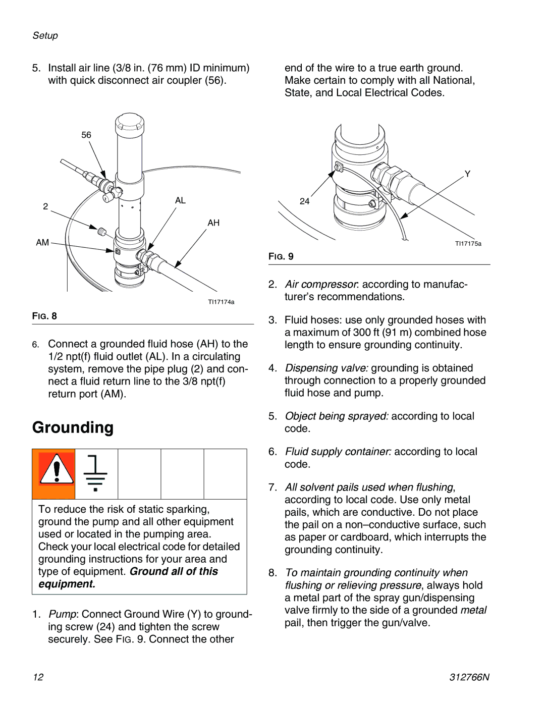
5.Install air line (3/8 in. (76 mm) ID minimum) with quick disconnect air coupler (56).
end of the wire to a true earth ground. Make certain to comply with all National, State, and Local Electrical Codes.
56
Y
2
AL
AH
24
AM
TI17174a
FIG. 8
6.Connect a grounded fluid hose (AH) to the 1/2 npt(f) fluid outlet (AL). In a circulating system, remove the pipe plug (2) and con- nect a fluid return line to the 3/8 npt(f) return port (AM).
Grounding
To reduce the risk of static sparking, ground the pump and all other equipment used or located in the pumping area. Check your local electrical code for detailed
grounding instructions for your area and type of equipment. Ground all of this equipment.
1.Pump: Connect Ground Wire (Y) to ground- ing screw (24) and tighten the screw securely. See FIG. 9. Connect the other
TI17175a
FIG. 9
2.Air compressor: according to manufac- turer’s recommendations.
3.Fluid hoses: use only grounded hoses with a maximum of 300 ft (91 m) combined hose length to ensure grounding continuity.
4.Dispensing valve: grounding is obtained through connection to a properly grounded fluid hose and pump.
5.Object being sprayed: according to local code.
6.Fluid supply container: according to local code.
7.All solvent pails used when flushing, according to local code. Use only metal pails, which are conductive. Do not place the pail on a
8.To maintain grounding continuity when flushing or relieving pressure, always hold
a metal part of the spray gun/dispensing valve firmly to the side of a grounded metal pail, then trigger the gun/valve.
12 | 312766N |