Setup
The divider valve is shipped ready to install in your sys- tem. It has been
NOTICE
Do not install a divider valve into a system rated for more than the valve’s maximum operating pressure. This type of installation could result in
To install the divider valve in your system:
1.Determine an appropriate, remote mounting loca- tion.
2.Install a rupture to atmosphere fitting with a
3.Install an analog pressure gauge at the inlet to the divider valve.
4.Install a slow or no cycle shutdown in one of the pis- ton enclosure plugs. Program it to shut down after no more than 180 seconds without a complete cycle.
5.Torque. See Table 4 on page 15.
As long as lubricant is supplied under pressure to the inlet section of the divider assembly, valves sections will continue to operate in a progressive manner. Divider assemblies always follow a constant discharge pattern. Whenever lubricant flow ceases, the valving pistons will stop. When flow resumes, it will start again at the same point in the discharge cycle.
Setup
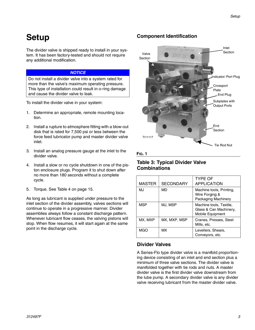
Component Identification
| Inlet |
Valve | Section |
| |
Section |
|
| Indicator/ Port Plug |
| Crossport |
| Plate |
| End Plug |
| Subplates with |
| Output Ports |
End
Section
TI11117
Tie Rod Nut
FIG. 1
Table 3: Typical Divider Valve
Combinations
|
| TYPE OF |
MASTER | SECONDARY | APPLICATION |
|
|
|
MJ | MD | Machine tools, Printing, |
|
| Wire Forging & |
|
| Packaging Machinery |
|
|
|
MSP | MJ, MSP | Machine tools, Textile, |
|
| Glass & Can Machinery, |
|
| Mobile Equipment |
|
|
|
MX, MXP | MX, MXP, MSP | Cranes, Presses, Steel |
|
| Mills, etc. |
|
|
|
MGO | MX | Levellers, Shears, |
|
| Conveyors, etc. |
|
|
|
Divider Valves
A
312497F | 3 |