Setup
Valve Sections (MSP, MHH and MXP
Valve sections (three or more required per manifold) contain a piston specially fitted to that section, built in outlet check valves and various passageways that, working with the piston, meters and valves the flow of lubricant (FIG. 2).
Piston
Enclosure/End
Plug
Enclosure Plug Gasket
Piston
Check
Valve
Indicator | TI11102 |
Port | Indicator Port Plug |
FIG. 2
Valve sections may be manufactured to require one or two lube outlets. Stamping located on the face of each section indicates:
•the style of divider valve section, i.e., MSP, MX, etc.,
•the discharge per piston stroke expressed in thousandths of cubic inches (35 = .035 in3 ) and,
•the number of lube outlets required (S = single, one outlet only; T = twin, two lube outlets required).
Prefilling Lubricant Distributor Lines
Follow the following procedure exactly as written, in the order written.
NOTICE
•The initial startup and operation is the most critical operating period for a newly installed machine in terms of potential for being damaged by unre- moved/unfiltered lubricant contaminants and lack of adequate lubrication. Proper prefilling of lubrication system ensures that lubricant is immediately avail- able to every lube point during machine startup, protecting them from damage.
•Use only clean oil filtered to the SAE
Filling Secondary-to-Lube Point Lines
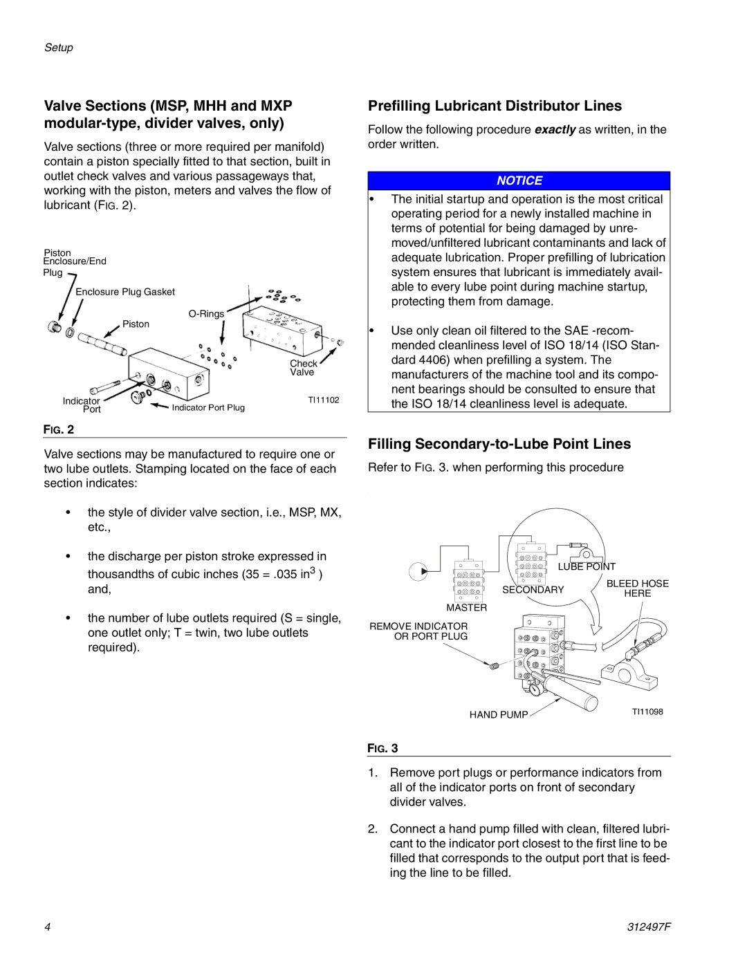
Refer to FIG. 3. when performing this procedure
.
LUBE POINT
BLEED HOSE
SECONDARYHERE
MASTER
REMOVE INDICATOR
OR PORT PLUG
HAND PUMP | TI11098 |
|
FIG. 3
1.Remove port plugs or performance indicators from all of the indicator ports on front of secondary divider valves.
2.Connect a hand pump filled with clean, filtered lubri- cant to the indicator port closest to the first line to be filled that corresponds to the output port that is feed- ing the line to be filled.
4 | 312497F |
