Installation
Typical Installation
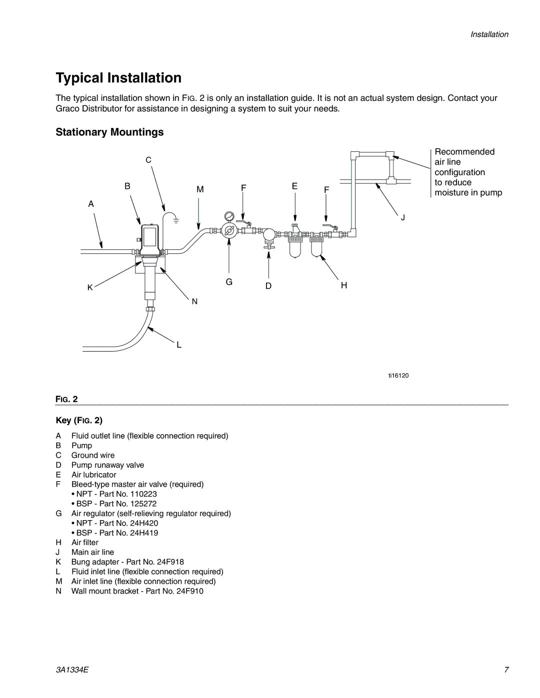
The typical installation shown in FIG. 2 is only an installation guide. It is not an actual system design. Contact your Graco Distributor for assistance in designing a system to suit your needs.
Stationary Mountings
C
BM FE F
A
J
Recommended air line configuration to reduce moisture in pump
K
G DH
N
L
ti16120
FIG. 2
Key (FIG. 2)
AFluid outlet line (flexible connection required)
BPump
CGround wire
DPump runaway valve
EAir lubricator
F
•NPT - Part No. 110223
•BSP - Part No. 125272
GAir regulator
•NPT - Part No. 24H420
•BSP - Part No. 24H419
HAir filter
JMain air line
KBung adapter - Part No. 24F918
LFluid inlet line (flexible connection required)
MAir inlet line (flexible connection required)
NWall mount bracket - Part No. 24F910
3A1334E | 7 |