Installation
Installation Guidelines
Reference letters found in the following instructions, refer to Typical Installation diagram provided on page 7.
•A ball valve must be installed upstream of the regu- lator (G).
•The fluid outlet line (A), fluid inlet line (L) and air inlet line (M) must be flexible (such as a hose).
NOTE: To prevent damage to the pump, remove sedi- ment from the bottom of the container before installing a pump on an existing container.
The maximum working pressure of each pump in your system may not be the same. To reduce the risk of
•Never exceed the maximum working pressure of the lowest rated component connected to a partic- ular pump.
•Be sure you know the maximum working pressure of each component.
•Do not exceed the maximum pump cycle rate.
•Regulate air pressure to prevent over pressuriza- tion at fluid section of the pump.
•Regulate air pressure to the pump so that no fluid line component or accessory is over pressurized.
Stationary Mounting Layout
Plan the layout for easy operator access to the pump air controls, sufficient room to change drums and a secure platform.
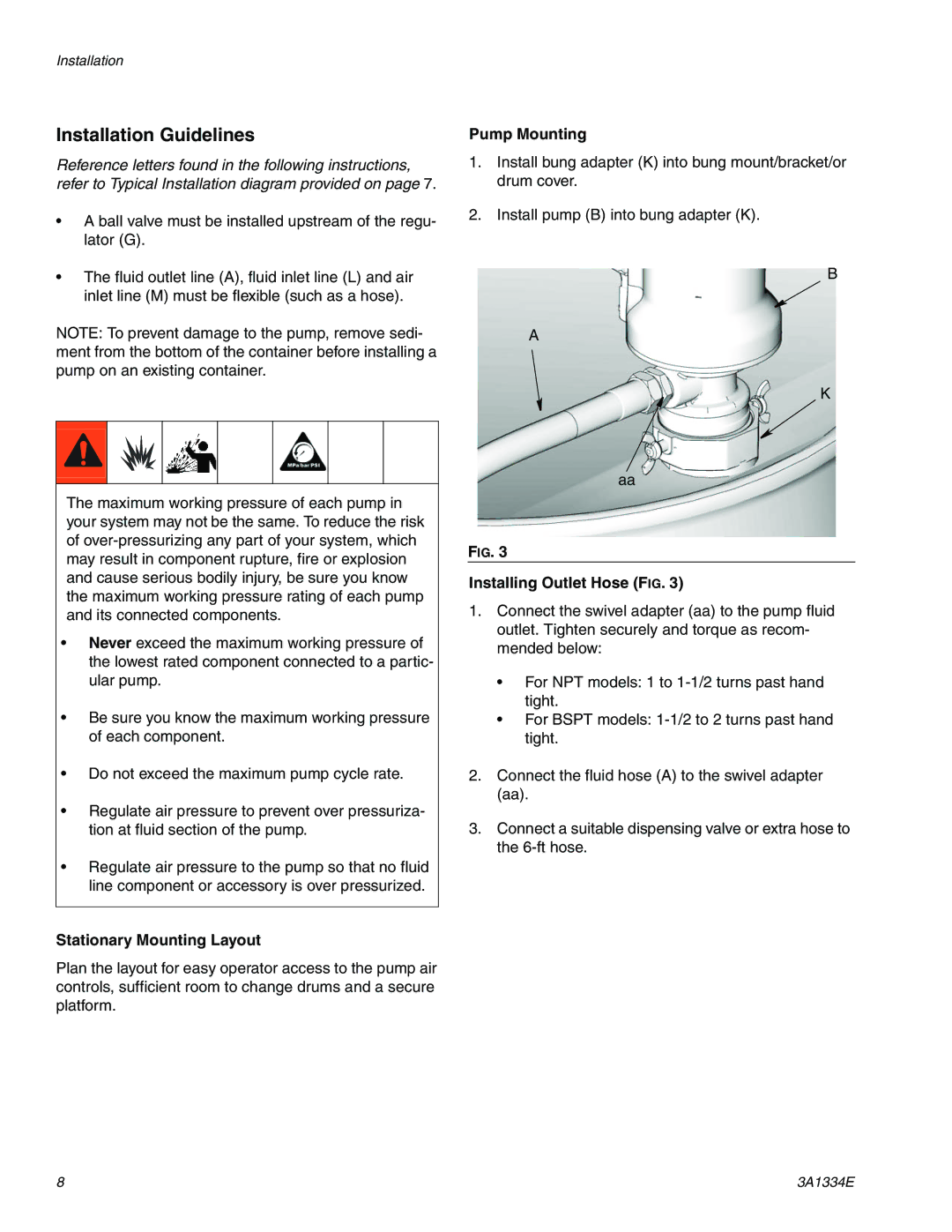
Pump Mounting
1.Install bung adapter (K) into bung mount/bracket/or drum cover.
2.Install pump (B) into bung adapter (K).
B
A
K
aa
FIG. 3
Installing Outlet Hose (FIG. 3)
1.Connect the swivel adapter (aa) to the pump fluid outlet. Tighten securely and torque as recom- mended below:
•For NPT models: 1 to
•For BSPT models:
2.Connect the fluid hose (A) to the swivel adapter (aa).
3.Connect a suitable dispensing valve or extra hose to the
8 | 3A1334E |